Virtual Channels Hardware Support in Switches in Relation to NoC Costs, Functions and Features
By Elena Suvorova, Yuriy Sheynin, Nadezhda Matveeva, Artur Eganyan
St. Petersburg University of Aerospace Instrumentation.
St. Petersburg, Russia
Abstract:
In many novel networks-on-chips (NoC) the virtual channels mechanism is widely used [1,5]. It could be used for different goals from livelocks avoidance to different classes of traffic support [1,2,3,4,5].
This mechanism could be differently implemented in hardware. The hardware costs and functional features with virtual channels depend on an approach to its hardware implementation [2,6]. In this article we consider dependencies between virtual channels hardware implementation features and packet transmission timing parameters in a network-on-chip, as well as possibilities for different classes of services support.
INTRODUCTION
The figure 1 represents a variant of a typical switch logical structure that supports virtual channels [2].
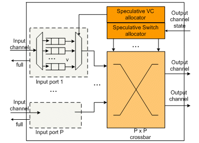
Figure 1. A typical switch logical structure
When the mechanism of virtual channels is used, from a logical point of view, a separate buffer space corresponds to every virtual channel. But at the hardware level different schemes could be used.
For example, a physically independent block of two-port memory could be used for every virtual channel, [7,8]. A modification of this approach uses a separate physical memory block for every buffer, while a virtual channel could include several buffers [7,8] (see figure 2 a, b).
In another approach all virtual channels use one two-port memory block, which is logically divided into some fragments (see figure 2 c). Every fragment corresponds to one virtual channel (or one buffer, when the virtual channel includes some buffers, [7,8]). Some hybrid variants of virtual channels hardware implementation with an intermediate position between these approaches could be used also, [7,8].
For a NoC routing switch it’s typical to have a single connection point to an external interconnection line for every input or output port.
However, switch port connection to the switching matrix for these approaches could be essentially different. For the first approach in a routing switch somewhat data packets could be simultaneously transferred from several virtual channels of the same input port to different output ports (typical port structure for this case is represented at the figure 2.b).
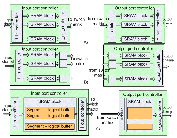
Figure 2. Some variants of buffer memory structure
The number of connection points of one port to switch matrix for the first approach could be from one to the number of memory blocks in the port (in most implementation its number in input port and output port is equal). If the number of connection points is less than the number of virtual channels, the virtual channels could be differently bound to it. A virtual channel could have fixed bound to the concrete connection point or could be bound dynamically to any connection point that is free for data transfer at that time.
Increase of connection point number allows to decrease packet transmission time and to raise communication system throughput. If output ports, for which the packets in buffers of different virtual channels lie, are free, these packets could be transmitted via different connection points simultaneously. It allows decreasing packet waiting time in input port buffers and correspondingly the packet transmission time. However a connection point number increase lead to hardware costs increase.
The second approach is to have a single connection point.
The possibility of simultaneous data packet transfers from some virtual cannels of one input port should be implemented in the switch matrix also. It should have the correspondent number of channels that connect the input ports with the output ports. Hardware costs for it are a considerable factor at the network-on-chip scale. Relation between availability of packet delivery schemes and support of different classes of services in a NoC is very important in network-on-chip design.
In a routing switch the virtual channels’ buffer memory could be placed in input ports, in output ports or both in input and output ports. Hardware cost and different functional features of virtual channels depend on placement of buffer memory in the switch.
In the article we consider different variants of virtual channels hardware implementation in routing switches as well as intermediate variants also (when the number of memory blocks and number of correspondent connections to the switch matrix is more than one but less than the number of virtual channels in one port). We consider switches that include buffer memory in both input and output ports.
We evaluate hardware cost for these variants, average and maximal packet transmission time via routing switch for data packet flows with different parameters. Then we evaluate possibility of different traffic classes support, bind it with guaranteed packet transmission time and guaranteed channel throughput.
VARIANTS OF CONSIDERED STRUCTURES
In this consideration we suppose that a packet is transferred via switch matrix as a unit, its transmission could not be interrupted by another packet (for example, packet witch higher priority). We do not consider multicast data packet transmission that isn’t used in NoC practically, [8].
In the research we suppose that all packets have fixed length. One packet is placed in one buffer (buffer size is equal to packet size.). One or several buffers could correspond to one virtual channel. A memory block could be divided to buffers physically or logically.
We compare several variants of a routing switch structure. In our numerical experiments we use the following assumptions. Number of switch’s ports is 4, 8, 16; number of virtual channels in one port is in the range from 2 to 8. Every virtual channel is bound with one priority level. All virtual channels have different priority levels; the number of a virtual channel is equal to the priority index. A virtual channel could have from one to four buffers. Size of one buffer is equal to the packet size and is 64 bytes. The number of one port’s connection points to the switch matrix is from 1 to 8.
In a system with a single connection point per port data packets from all the port virtual channels are transmitted via this connection point one by one correspondingly with a virtual channel priority level.
HARDWARE COST EVALUATION
Let’s evaluate hardware cost of routing switches with different number of ports, different number of virtual channels in every port, different number of buffers in every virtual channel and different number of connection points from a port to the switch matrix. Parameters are given in the table.
| Parameter | Description |
| Np | Number of ports in routing switch |
| Nt | Number of connection points to switch matrix for one port (input or output) |
| Nch | Number of channels, connected to one port (input and output channels) |
| Nvch | Number of virtual channels |
| Nm | Number of channels in switch matrix |
| Nbi | Number of buffers in one port (input) |
| Nbo | Number of buffers in one port (output) |
| Zc | Area of one SRAM cell (6 transistors) |
| Zl | Area of one logic gate (4 transistors) |
| Zd | Area rate of logic gate and SRAM cell |
| Nw | Number of bits in one word (data channel width) |
| Na | Number of additional bits for every word (such as flag of packet’s end, byte valid flags) |
| Nf | Number of additional bits for flow control (for example data strob, and data acknowledge) |
| Nv | Number of words in one buffer |
| Zb | Area of one buffer |
| Zbs | Summary area of buffers of all ports |
| Zch | Area of one channel in switch matrix |
| Zm | Area of switch matrix |
| Cic|Zic | Number of logic gates | area in one i_in_controller (input port) |
| Cio|Zio | Number of logic gates | area in one i_out_controller (input port connection point) |
| Coa|Zoa | Number of logic gates | area in one arbiter (output port connection point) |
| Coc|Zoc | Number of logic gates | area in o_out_controller (output port) |
| Zp | Summary area of ports controllers logic |
| Zrsw | Summary area of routing switch |
Buffer hardware cost is regarded to be not dependent on its physical structure (one memory block with logical division or some memory blocks). Summary number of memory cells and number of additional logic (read/write pointers) in both cases are equal. When buffer size is more than 16 words a hardware cost of additional logic is negligible small (less than 5% of the whole hardware cost and this value is quickly decreased with buffer size increasing).
The summary area of buffers of all ports could be evaluated as:

Area of one buffer is:

Number of channels of switch matrix connected to one port (in both directions of the port) is:

Number of channels in switch matrix (every connection point connected with every other connection points):

Area of switch matrix is estimated as:

The area of the i_in_controller component (figure 2) in a general case depends on a number of buffers in one port, a packet header format, and an algorithm of buffer selection for this packet.
The area of the component i_out_controller (figure 2) in a general case depends on a connected to this controller number of buffers, on the next packet for transmission selection algorithm and on a number of arbiter components in that it could translate data packets (that is equal the number of output port connection point with that it is bind).
The area of the component “arbiter” (figure 2) in a general case depends on the number of buffers that are connected to the controller, on the number of i_out_controller components, from which it could receive data packets, and on the arbitration algorithm.
The area of the o_out_controller component (figure 2) in a general case depends on the number of buffers in one port and on the algorithm of selection of next packet for transmission.
We don’t take into account a hardware cost of state and operation mode registers, routing table in a routing switch because it strongly depends on specific data transmission protocol in concrete network-on-chip.
Let’s evaluate hardware cost of a routing switch where any buffer could be connected to any connection point (both for an input port and for an output port). At the logical level this hardware implementation could correspond to a system, in which a number of buffers that is bound to every virtual channel could be changed dynamically (or in system initialization time). In such a switch every connection point of every input port could be connected to every connection point of every output port in switch matrix. For this implementation variant (1) hardware cost could be evaluated by:

where

Let’s evaluate hardware cost of a routing switch implementation, in which every connection point is bound with a fixed number of buffers. At the logical level this implementation means that a set of buffers is bound to a virtual channel (or to a group of virtual channels, data transmission from which goes via one connection point) is fixed at the system development stage. In this case hardware cost of i_out_controler and the arbiter will be less than for the implementation variant (1), due to decreasing number of buffers that are connected to every of these components.
In some cases in such switches connection points connected in routing switches with scheme “every with every”. On logical level the possibility of data transmission on network level inside switch from one virtual channel to other (for example if one class of service bind with some virtual channels) exists in this case.
Let denote hardware cost of the connection point i components as Zio_i and Zoa_i. For such a routing switch implementation (variant 2) hardware cost of port controllers could be evaluated by:

Summary hardware cost for this implementation could be evaluated by the formula (6) in that Zp is calculated by the equation (8).
In routing switches, where a data packet is fixed to a virtual channel (also on network layer) we don’t need to connect every connection point of every input port with every connection point of every output port. Only connection points that correspond to the same virtual channel are connected. In this case the switch matrix could be divided into independent submatrixes with lesser number of channels. The number of channels in this switch matrix:

Summary hardware cost of this implementation (variant 3) could be evaluated with the formula (6) in which Zp is calculated by the equation (8), Zm – by the equation (5) with Nm value calculated by equation (9).
On figure 3 the hardware costs of routing switches for three considered implementation variants as the function of port number and for different connection point number are represented. These parameters are derived for Zl=0,35um2, Zc=0,12um2, that are typical area of these component on 2010 year by information of ITRS [9]. At the figure 4 hardware costs without buffers area are estimated.
On figure 4 the hardware cost of combination logic of routing switches (without taking into account buffers) as the function of port number and for different connection point number are represented.
If number of buffers in every port is not bigger than 4, the hardware implementation cost (when buffer size is 64 words) are 10 – 30 % of summary hardware cost. When number of buffers is from 8 to 32 the hardware cost of its implementation is up to 50% of the summary hardware cost.
The function of hardware cost (with/without buffers) from the port number is near to quadratic (On 10% less than quadratic, due to port controllers whose dependency is essentially less than quadratic) for all implementation variants. The function of hardware cost from the connection points number is near to quadratic also.
With 4 ports hardware costs for the Variant 1 are 2 times more than the costs for the Variant 2. However, with increase of the port number a difference diminishes and tends to 1,2 at 32 ports.
Hardware costs for the Variant 2 excess costs for the Variant 3; difference increases with increase of number of ports and number of connection points. For instance, with 4 ports sots ratio is 1,1, while with 32 ports and with 8 connection points the ratio is about 3.
Thus, with small number of ports (up to 8) we have minor difference in hardware costs for all the 3 variants. With higher number of ports hardware costs for the variant 3 shows to be considerably less; though variant 3 has functional limitations in its operation.
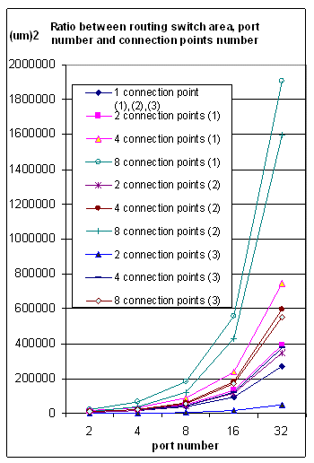
Figure 3. Ratio between routing switch area and ports number, connection points number.
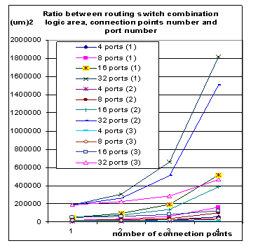
Figure 4. Ratio between routing switch combination logic area and ports number, connection points number.
PACKET TRANSMISSION TIME EVALUATION
Average packet transmission time in relation to the number of bound to a virtual channel buffers and packet flow rate for the case of a switch with 4 virtual channels and 16 buffers is illustrated at the figure 5 (one connection point) and figure 6 (two connection points). For other number of ports, buffers and connection points we shall see similar trends.
On these charts the results for uniform and exponential distributions of packet generation time are represented; input ports’ load is 70% and 90%. The highest priority corresponds to the virtual channel with number 0. In the chart legend the first digit corresponds to the number of virtual channel, then goes the input port load, type of packet generation time distribution, then number of connection points.
If packet generation time has exponential distribution then the average packet transmission time is practically equal for all virtual channels, it weakly depends on ratio between density of bound to different virtual channels packets in input packet flow, to number of buffers in these virtual channels.
In case of uniform distribution of packet generation time the average packet transmission time more essentially depends on ratio between density of packets bind to different virtual channels in input packet flow and number of buffers in these virtual channels. However in this case the packet transmission time dispersion does not exceed 1,5 times with input port load 90% and 1,1 times with input port load 70%, both with one and two connection points.
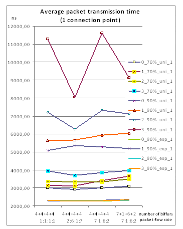
Figure 5 Average packet transmission time as function from number of buffers and packet flow rate (1 connection point)
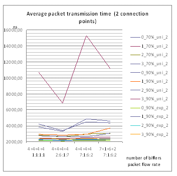
Figure 6. Average packet transmission time as function from number of buffers and packet flow rate (2 connection point)
Dependency between number of buffers in a virtual channel and average packet transmission time with different flow ratios in different virtual channels is illustrated on figure 7. Plots at this figure show that when the number of buffer grows from one to four the average packet transmission time decreases 2,8 times. Number of buffers growth from one to two gives the average packet transmission time decrease 2,2 times. Further increase of the number of buffers doesn’t give considerable gain in packet transmission time.
Thus for relation between average packet transmission time and hardware cost of the best ratio between number of connection points and number of buffers showed to be 1:2 or 1:4. This trend is true for other numbers of connection points and other numbers of ports in switches also. .
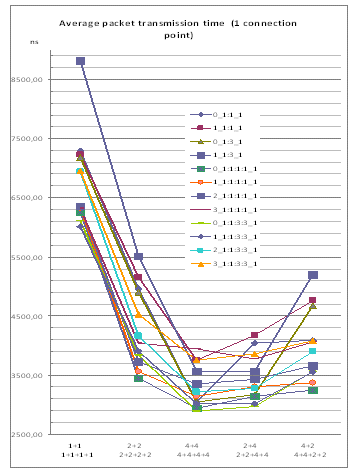
Figure 7. Average packet transmission time (2 and 4 virtual channels, 1 connection point)
The ratio between number of connection points and average packet transmission time is illustrated by the plot represented at the figure 8.
The average packet transmission time is most essentially reduced– in factor of two, with increasing of connection points number from one to two, especially for uniform distribution of packet generation time. Further increase of connection points number gives practically no further decrease in the average packet transmission time.
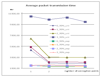
Figure 8. Ratio between average packet transmission time and number of connection points
CONCLUSION.
With presented investigations we can define for NoC interconnections with virtual channels reasonable ranges of switch configurations and parameters could be classified in regard to for showed that:
- The variant of a routing switch implementation with smallest hardware cost (variant 3) is good for NoC with exponential distribution of data packet generation time. It works without essential degradation of parameters even if data flows ratios to different virtual channels not corresponds number of buffers in these virtual channels.
- For average packet transmission time characteristic the ratio of 2 or 4 buffers per one connection point would be the best.
- It is enough two connection points to one port, the next increasing of its number not leads to decreasing of average packet transmission time.
- For NoC with exponential distribution of data packet generation time two buffers per virtual channel shows to be enough; further number of buffers increase does not give essential reduces of packet delivery time.
REFERENCES
- W. J. Dally, B. Towles. Principles and practices of interconnection networks. Elsevier 2004, 550p
- Yuriy Sheynin, Elena Suvorova Networks-on-Chip with Reprogrammable Interconnections (http://www.design-reuse.com/articles/20887/networks-on-chip-reprogrammable-interconnection.html)
- Methods of selection of structural and architectural organization of multicast switches. Yuriy Sheynin, Elena Suvorova. IP-SOC 2006 (IP Based SoC Design Conference & Exibition Dec. 7-8, 2006 France)
- ViChaR: A Dynamic Virtual Channel Regulator for Network-on-Chip Routers. In Microarchitecture, 2006. MICRO-39. 39th Annual IEEE/ACM International Symposium
- A. Mello, L. Tedesco, N. Calazans, and F. Moraes. Virtual channels in networks on chip: Implementation and evaluation on hermes NoC. In SBCCI ’05: Proceedings of the 18th annual symposium on Integrated circuits and system design, pages 178–183, New York, NY, USA, 2005. ACM Press
- S. Vangal et al., "An 80-Tile 1.28 TFLOPS Network-on-Chip in 65nm CMOS," Solid-State Circuits Conference, 2007. Digest of Technical Papers. IEEE International, pp. 98-589, 2007
- G. Michelogiannakis, J. Balfour, and W. J. Dally. Elastic-buffer flow control for on-chip networks. In HPCA-15, 2009.
- Wu, Sung-Tze Chao, Chih-Hao Wey, I-Chyn Wu, An-Yeu Dynamic Channel Flow Control of Networks-on-Chip Systems for High Buffer Efficiency. Signal Processing Systemc, 2007 IEEE Workshop
- ITRS 2010.
Related Semiconductor IP
- HBM4 PHY IP
- Ultra-Low-Power LPDDR3/LPDDR2/DDR3L Combo Subsystem
- MIPI D-PHY and FPD-Link (LVDS) Combinational Transmitter for TSMC 22nm ULP
- HBM4 Controller IP
- IPSEC AES-256-GCM (Standalone IPsec)
Related Articles
- Virtual Prototyping Environment for Multi-core SoC Hardware and Software Development
- Leveraging virtual hardware platforms for embedded software validation
- Improving Software Driver Development and Hardware Verification Productivity using Virtual Platforms
- How to make virtual prototyping better than designing with hardware: Part 1
Latest Articles
- A 14ns-Latency 9Gb/s 0.44mm² 62pJ/b Short-Blocklength LDPC Decoder ASIC in 22FDX
- Pipeline Stage Resolved Timing Characterization of FPGA and ASIC Implementations of a RISC V Processor
- Lyra: A Hardware-Accelerated RISC-V Verification Framework with Generative Model-Based Processor Fuzzing
- Leveraging FPGAs for Homomorphic Matrix-Vector Multiplication in Oblivious Message Retrieval
- Extending and Accelerating Inner Product Masking with Fault Detection via Instruction Set Extension