USB4 Port Operations
Designs are tested in the labs for various electrical compliance tests defined in the electrical compliance test specifications before getting certified. There are defined processes and steps that a design must go through for such testing. Such tests are focused tests and need complete control of the specific parts of the design to do targeted testing with the generated stimulus. Hence, they are done outside of the normal protocol flow by bringing the specific part of a design under test in a defined condition and getting it ready. To do so, protocol specifications define compliance operations.
Even though these compliance tests are mostly electrical in nature, the design under test still needs to go through defined logical steps to get the specific part ready for the test, to provide the stimulus, and to measure the effect of that stimulus.
USB4, too, has defined compliance port operations. These port operations are used to bring transmitters and receivers of a design under test into compliance mode and to execute tests like bit error tests, burst error rate tests, clock switch tests, TxFFE equalization tests, electrical Idle tests, etc.
Various compliance port operations and their respective intents are listed in the table below,
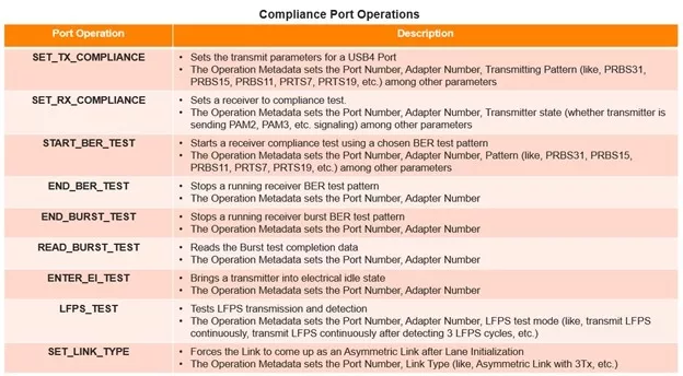
The SET_TX_COMPLIANCE port operation provides the flexibility to have a USB4 Port transmit the various possible patterns that are required for the transmitter compliance testing. These patterns encompass Gen2, Gen3, and Gen4 link speeds. For Gen2/Gen3, they are PRBS31, PRBS15, PRBS9, PRBS7, SQ2, SQ4, SQ32, SQ128, SLOS1. For Gen4, they are PRBS11, PRTS7, PRTS19, STAIRS112, SQ224. The applicability of when to use which pattern depends on the test defined in the electrical compliance test specification. It varies according to the test objectives.
The SET_RX_COMPLIANCE port operation puts a receiver to the compliance test. It provides the option to indicate to the receiver whether the transmitter is transmitting PAM2 or PAM3 encoded data. The transmitter knows when to switch the transmitting pattern through the completion data of this port operation at the receiver. This completion data indicates whether the receiver is ready for PAM3 and SSC activation.
The LFPS_TEST port operation is used to test the transmitter and receiver of LFPS signaling. It provides various modes for LFPS transmission, i.e., to transmit 100 cycles of LFPS, transition to electrical idle for tPreData, and start sending SLOS1 (for Gen2 or Gen3) or PRBS11 (for Gen4). Such modes help test the LFPS scenarios that are part of the protocol flow.
The port operations are applicable whether the link is symmetric or asymmetric for Gen4 link speed. For testing an asymmetric link SET_LINK_TYPE port operation is used to force the link to come up as an asymmetric link after lane initialization before using other port operations.
Compliance testing involves compliance software to test a Port Under Test (PUT). VIP has appropriate controls to mimic a PUT and functionality of compliance software.
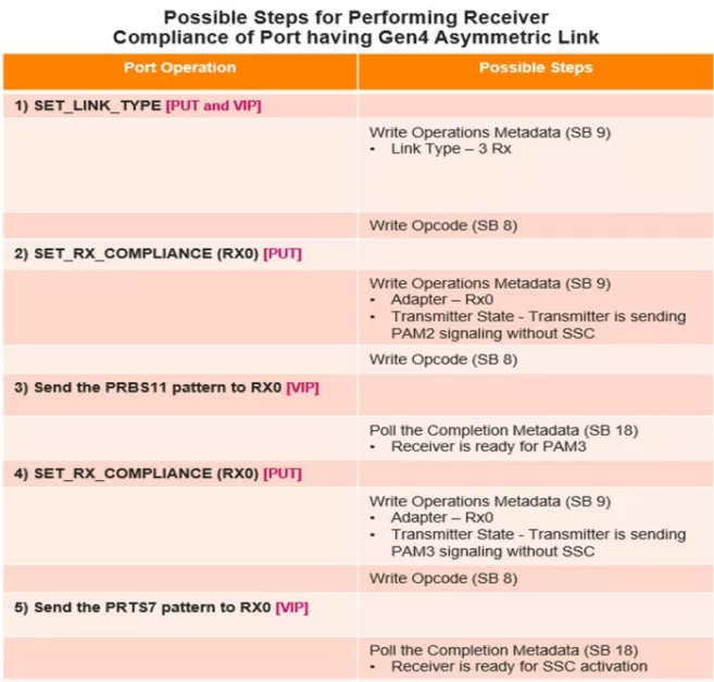
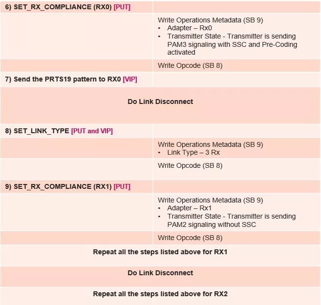
An example flow for checking the receiver compliance of the Rx adapters of a Gen4 asymmetric link is depicted in the table below. In this, the PUT is to be tested for receiver compliance, with VIP being used to send the relevant test patterns to the adapters of the PUT.
In addition to the compliance port operations, there are a few service port operations as well that are required. They are ROUTER_OFFLINE_MODE to put a USB4 port in offline mode, ENUMERATE_RE-TIMERS to cause a USB4 port to send a broadcast RT transaction, and FEC_ERRORS_STAT to start, stop, and read the FEC errors counters of a port.
Before a port operation can be initiated, its metadata and data should be programmed in the relevant sideband registers. Sideband registers 8, 9, and 18 are used for this purpose, namely for writing the opcode, metadata, and data or completion data of a port operation, respectively. The type of metadata that is required is as mentioned in the table above. It influences the ways a port operation executes the intended test objectives.
Cadence has a mature verification IP solution for the verification of various aspects of USB4 version 2.0 and version 1.0 design, with verification capabilities provided to do a comprehensive verification of these.
You may refer to https://www.cadence.com/en_US/home/tools/system-design-and-verification/verification-ip/simulation-vip.html for more information.
Related Semiconductor IP
- Simulation VIP for USB4
- USB4 PHY - TSMC N4P 1.2V, North/South Poly Orientation
- USB4 PHY - TSMC N3E 1.2V, North/South Poly Orientation
- USB4 PHY - TSMC N3P 1.2V, North/South Poly Orientation
- USB4 VIP
Related Blogs
- USB 3.0 IP on FinFET may stop port pinching
- How to Use the AXI VIP Debug Port
- USB4: Higher Performance and Combined Data, Display, and Power
- Cadence Leads the Pack: The First VIP for USB4 is Here!
Latest Blogs
- Ensuring reliability in Advanced IC design
- A Closer Look at proteanTecs Health and Performance Management Solutions Portfolio
- Enabling Memory Choice for Modern AI Systems: Tenstorrent and Rambus Deliver Flexible, Power-Efficient Solutions
- Verification Sanity in Chiplets & Edge AI: Avoid the “Second Design” Trap
- Embedded Security explained: Cryptographic Hash Functions