Understanding Timing Correlation Between Sign-off Tool and Circuit Simulation
By Sapana Maurya, Sunil Chaudhary (eInfochips)
1- Introduction
For lower technology node designs, it is recommended to use CCS (Composite Current Source) timing libraries because NLDM (Non Linear Delay Model) libraries are unable to model high interconnect impedance, noise propagation and physical effects such as the Miller effect. This inaccurate cell delay calculation necessitates the use of CCS timing libraries.
CCS timing libraries have larger file sizes than NLDM libraries, resulting in longer run times and higher memory usage during the physical implementation stage.
However, establishing better correlation between the sign-off tool and circuit simulations (HSPICE) within an acceptable accuracy range is crucial to ensure the quality of the design.
As a result, the question arises regarding the timing correlation due to the different timing models used during the implementation and sign-off stages.
To address this problem, tighter accuracy is required due to reduced technology margin allowances. Verifying the accuracy of CCS timing libraries on sign-off tool becomes essential to obtain accurate results during the physical implementation stage.
This article presents Timing Correlation Analysis between the sign-off tool and HSPICE for the design of a 5nm technology node. We will explore several types of Timing Correlation Analysis and define the accuracy of libraries based on the correlation results.
2- Timing Correlation Flow
During the design flow, after library characterization, it is necessary to perform library validation before initiating Timing correlation. This validation is useful to confirm the quality of CCS timing and noise data in the libraries.
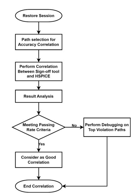
To perform this validation, you can use the available EDA Tool by Synopsys Library Compiler. After the library validation, Timing Correlation can be performed on these validated libraries. The Timing Correlation Flow is shown in the figure below:

Figure. Timing Correlation Flow
2-1- Accuracy Correlation Criteria
The following table shows the considered criteria for accuracy correlation:

Table-1. Accuracy correlation criteria
2-2- Path Selection for Accuracy Correlation
Selection of paths for Non-coupled Correlation:
This section provides guidelines to select paths for accuracy correlation. Firstly, select a fixed number of paths randomly, and then filter the paths according to the given conditions/criteria:
- Paths that are in a loop can cause simulation issues and should be removed from the selection.
- The endpoint should not be an asynchronous pin.
- The endpoint and startpoint should not be the same cell.
- There should not be any case value at the register D pin.
Selection of pins for Coupled Correlation:
- We must have a set of input pins before starting coupled delay or noise calculation to perform accuracy correlation.
- Collect nets that have a large crosstalk delta or crosstalk bumps in the design.
- For example, the sign-off tool has a command to separate nets with a large crosstalk delta on setup paths with slack less than 0.
Selection of paths for POCV Correlation:
For POCV correlation, we must select paths with good non-coupled path correlation results. Poor non-coupled correlation can affect POCV correlation results.
The criteria for selecting such paths are:
- HSPICE correlation error should be within the permissible limit.
- Paths should have a reasonable number of stages, neither too short nor too long with respect to logic depth. Short paths make it hard to achieve reasonable correlation, while long paths result in longer simulation runtimes.
- All paths should have reasonable variation, with a small ratio of POCV to non-occupied path arrival.
2-3- Types of Accuracy Correlation
2-3-1- Non-coupled Path Correlation:
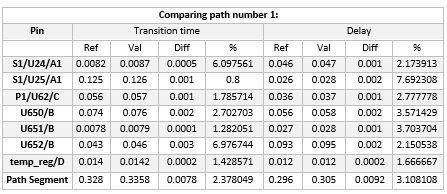
Non-coupled or without coupling effect path correlation can be performed after selecting a set of paths for accuracy correlation. The data from HSPICE simulations and the data arrived from the reports of sign-off tool need to be compared to correlate both sets of data.
An example is shown below:

Table-2. Non-coupled path correlation
Capture Clock Path Accuracy Correlation:
- Similarly, you require a CRPR common point and an endpoint clock pin for non-coupled clock path accuracy correlation. Same as non-coupled, we need to correlate the data. The only difference here is the path is capture clock path instead of data path.
2-3-2- Crosstalk/Coupled Delay Correlation:
- Crosstalk/Coupled Delay occurs when both aggressor and victim nets switch together.
- Coupled correlation is performed based on rise and fall values, and delay measured from the input of the driver to the input of the receiver.
2-3-3- Crosstalk Noise Correlation:
- Crosstalk Noise occurs when the aggressor net is passing a steady signal and the victim nets are switching.
- We can use the above criteria to select pins for noise correlation.
- Perform crosstalk noise correlation based on height and area accuracy on the corresponding nets. We should have a list of input pins for which to perform accuracy correlation.
2-3-4- POCV Path Correlation:
- Before starting POCV path correlation, you should have a list of selected paths for accuracy correlation. Follow the guidelines and recommendations mentioned in the Path Selection for Accuracy Correlation section to select a good set of paths for POCV correlation.
- The ratio of path arrival (with variation) over nominal path arrival (without variation) should be less than 2.0. After you get a list of selected paths, you can perform POCV path correlation.
2-4- Debugging Violating Paths:
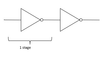
- One stage analysis = Driver input to Driver output

One stage Correlation Report

- One and half stage analysis = Driver input to Receiver output

1.5 stage Correlation Report

- Identify the stages significantly causing the miscorrelation of a path from the reports.
- To debug a single path, make 1 stage and 1.5 stage analysis by using CCS and NLDM model as well and observe the results, check the differences of both timing models.
- From the above example, we can see in the 1.5 stage correlation report, the delay difference is 5.21ps which exceeds the criteria limit as mentioned in the above Accuracy correlation criteria table-1, therefore, we need to perform cell characterization on the INV_1 inverter.
- If 10% of the total indices are failing, then the cell has a characterization issue, and report further about all those cells.
3- Conclusion
CCS Timing libraries are more accurate than NLDM Timing libraries, for lower technology node designs it is recommended to verify the accuracy of CCS timing libraries on signoff tool. Thus, to verify this, timing correlation analysis is done between the sign-off tool and HSPICE.
4- Authors
Sapana Maurya

Sapana Maurya works as a Physical Design Engineer at eInfochips. She holds a Master of Engineering degree in Signal Processing and VLSI Technology from Vishwakarma Government Engineering College in Ahmedabad, India. She has over 1 year of experience in ASIC design, including EDA Certification Activity, place & route, and STA analysis on Lower Technology Nodes.
Sunil Chaudhary

Sunil Chaudhary works as a Physical Design Engineer at eInfochips. He holds a Master of Engineering degree in Signal Processing and VLSI Technology from Vishwakarma Government Engineering College in Ahmedabad, India. He has over 2 years of experience in ASIC design, including EDA Certification Activity, place & route, and STA analysis on Lower Technology Nodes.
Related Semiconductor IP
- NPU IP Core for Mobile
- MSP7-32 MACsec IP core for FPGA or ASIC
- UHF RFID tag IP with 3.6kBit EEPROM and -18dBm sensitivity
- NPU IP Core for Edge
- Specialized Video Processing NPU IP
Related White Papers
- Static timing analysis: bridging the gap between simulation and silicon
- Preservation of Circuit Structure and Timing during Fault Emulation in FPGA
- Enhance circuit timing design with programmable clock generators (Part 1 of 2)
- Understanding DDR SDRAM timing parameters
Latest White Papers
- Ramping Up Open-Source RISC-V Cores: Assessing the Energy Efficiency of Superscalar, Out-of-Order Execution
- Transition Fixes in 3nm Multi-Voltage SoC Design
- CXL Topology-Aware and Expander-Driven Prefetching: Unlocking SSD Performance
- Breaking the Memory Bandwidth Boundary. GDDR7 IP Design Challenges & Solutions
- Automating NoC Design to Tackle Rising SoC Complexity