Critical Safety Overview and Definitions

Critical safety systems are necessary to prevent catastrophic outcomes. Achieving this requires a rigorous standards framework and documented processes addressing both hardware and software safety concerns. Safety-critical systems, governed by functional safety (FuSa) and industry-specific standards, protect lives, property, and the environment by ensuring that components or processes function correctly, even during faults. FuSa focuses on detecting, managing, or mitigating malfunctions in hardware and software to minimize the risk of failures and their consequences.
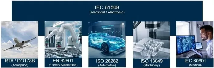
IEC 61508 is an international standard consisting of methods on how to apply, design, deploy, and maintain automatic safety-related protection systems. This is a basic functional safety standard applicable to all industries.
Using IEC 61508 as a starting point, each industry has evolved its own FuSa standard to focus on and address that industry’s unique requirements. These standards include RTA/DOI178B (Aerospace), EN 62601 (Factory Automation), IS0 26262 (Automotive), ISO 13849 (Machinery), and IEC 60601 (Medical).
This document provides an overview of the terminology, compliance requirements and system-level considerations for automotive critical safety, with a focus on ISO 26262. FuSa features are integral to every automobile, including the system-on-chip (SoC) devices for tasks such as sensor processing, sensor fusion, artificial intelligence (AI) and machine learning (ML).
ISO 26262 is an international standard for FuSa that is specifically designed for the automotive industry. The standard contains specialized terminology with acronyms and abbreviations that can be misinterpreted or forgotten. The following cheat sheet can be used as a quick reference to reduce confusion, improve efficiency and facilitate collaboration.
Functional Safety Acronym and Abbreviation Table Cheat Sheet
| Abbreviation | Meaning | Description | Standards Reference(s) |
|---|---|---|---|
| ASIL | Automotive Safety Integrity Level | One of four levels to specify the item’s (1.69) or element’s (1.32) necessary requirements of ISO 26262 and safety measures (1.110) to apply for avoiding an unreasonable residual risk (1.97), with D representing the most stringent and A the least stringent level. ISO 26262-9 describes ASIL analyses in detail! |
ISO 26262-1 1.6 ISO 26262-9 |
| ASIL Decomposition | Automotive Safety Integrity Level Decomposition | Also called “ASIL Tailoring.” Apportioning of safety requirements redundantly to sufficiently independent elements (1.32), with the objective of reducing the ASIL (1.6) of the redundant safety requirements that are allocated to the corresponding elements. “How to” example chart is in ISO26262-9 5.4.10 |
ISO 26262-1 1.7 ISO 26262-9 5 |
| AUTOSAR | Automotive Open System Architecture | Not in ISO 26262, “is an open and standardized automotive software architecture, jointly developed by automobile manufacturers, suppliers and tool developers.” | autosar.org wiki: AUTOSAR |
| CCF | Common Cause Failures | Failure (1.39) of two or more elements (1.32) of an item (1.69) resulting from a single specific event or root cause. Common cause failures are dependent failures (DF) (1.22) that are not cascading failures (CF) (1.13). |
ISO 26262-1 1.14 |
| CF | Cascading Failure | Failure (1.39) of an element (1.32) of an item (1.69) causing another element or elements of the same item to fail. Cascading failures are dependent failures (DF) (1.22) that are not common cause failures (CCF) (1.14). |
ISO 26262-1 1.13 |
| CMF | Common Mode Failure | A type of common cause failure (CCF) where multiple items fail in the same mode. Analyze it using fault tree analysis (FTA). | ISO 26262-10 B.3.2 |
| DC | Diagnostic Coverage | Proportion of the hardware element (1.32) failure rate (1.41) that is detected or controlled by the implemented safety mechanisms (1.111). | ISO 26262-1 1.25 ISO 26262-5 D |
| DCLS | Dual Core Lockstep | Processing system that runs the same set of operations at the same time in parallel. For ISO 26262 applications, the second “checker” core usually executes 1 or 2 clock ticks after the primary “reference” core to help ensure that power glitches will not simultaneously affect both cores, resulting in no detection of an error. |
wiki: Lockstep |
| DF | Dependent Failure | Failures (1.39) whose probability of simultaneous or successive occurrence cannot be expressed as the simple product of the unconditional probabilities of each of them. Dependent failures include common cause failures (CCF) (1.14) and cascading failures (CF) (1.13). ISO 26262-9 7 explains dependent failure analysis (DFA). |
ISO 26262-1 1.22 ISO 26262-9 7 |
| DFA | Dependent Failure Analysis | Aims to identify the single events or single causes that could bypass or invalidate a required independence or freedom from interference between given elements and violate a safety requirement or a safety goal. | ISO 26262-9 7 |
| DIA | Development Interface Agreement | Agreement between customer and supplier in which the responsibilities for activities, evidence or work products to be exchanged by each party are specified. An example DIA is at ISO 26262-5 B. |
ISO 26262 1.24 ISO 26262-8 5 |
| DTI | Diagnostic Test Interval | Amount of time between the executions of online diagnostic tests by a safety mechanism. Use ISO 26262-5 Table D.1 for analysis. |
ISO 26262-1 1.26 ISO 26262-5 D |
| E/E/PE | Electrical, Electronics, and Programmable Electronic | IEC 61508-4 3.2.6 defines this as based on electrical and/or electronic and/or programmable electronic technology. | IEC 61508- 3.2.6 |
| EMI | Electromagnetic Interference | Disturbance that affects an electrical circuit due to either electromagnetic induction or electromagnetic radiation emitted from an external source. | ISO 26262-2 wiki: Electromagnetic interference |
| EOS | Electrical Overstress | Electrical overstress failures can be classified as thermally-induced, electromigration-related and electric field-related failures. Can result in a latchup short circuit. Example of failure rate resulting from EOS is in ISO 26262-10 A.3.4.2.4. Calculation methods are in IEC TR 62380, “Reliability data handbook – Universal model for reliability prediction of electronics components, PCBs and equipment” |
ISO 26262-10 A.3.4.2.4 IEC TR 62380 wiki: Failure modes of electronics |
| ESD | Electrostatic Discharge | A subclass of Electrical Overstress (EOS). The sudden flow of electricity between two electrically charged objects caused by contact, an electrical short, or dielectric breakdown. See ISO 26262-5 E for example of SPFM and LFM calculations with ESD. |
ISO 26262-2 wiki: Electrostatic discharge |
| FIT | Failure In Time | The number of failures that can be expected in one billion (1×10^9) device-hours of operation. Mean time between failures (MTBF) = 1,000,000,000 x 1/FIT. |
ISO 26262-2 wiki: Failure rate |
| FMEA | Failure Mode and Effects Analysis | As opposed to fault tree analysis (FTA), failure mode and effects analysis (FMEA) is an inductive approach focusing on the individual parts of the system, how they can fail and the impact of these failures on the system. Analysis starts at faults, which can lead to errors and then failures. Can be qualitative or quantitative. |
ISO 26262-10 B wiki: Failure mode and effects analysis |
| FMEDA | Failure Mode Effects and Diagnostic Analysis | A procedure for the detailed determination of error causes and their impact on the system and can be very efficiently used in the early stages of systems development for the purpose of early identification of weaknesses. | TÜV NORD: FMEDA |
| FTA | Fault Tree Analysis | As opposed to failure mode and effects analysis (FMEA), fault tree analysis (FTA) is a deductive approach starting with the undesired system behavior and determining the possible causes of this behavior. Can be qualitative or quantitative. |
ISO 26262-10 B |
| FTTI | Fault Tolerant Time Interval | The time between when a fault occurs and the system can transition to a safe state and be ready to experience another possible hazard. Maximum FTTI = DTI + Fault Reaction Time + Safe State |
ISO 26262 1.44 |
| HSI | Hardware-Software Interface | Use ISO 26262-4 B for a detailed explanation. | ISO 26262-2 ISO 26262-4 B |
| LFM | Latent Fault Metric | Latent faults are multiple-point faults (1.77) whose presence are not detected by a safety mechanism (1.111) nor perceived by the driver within the multiple-point fault detection interval (MPFDI) (1.78). The latent fault metric (LFM) is a hardware architectural metric that reveals whether or not the coverage by the safety mechanisms, to prevent risk from latent faults in the hardware architecture, is sufficient. Single point fault metric (SPFM) is the other hardware architectural metric. · ASIL B (≧60%), C (≧80%) and D (≧90%) coverage requirements are in ISO 26262-5 8.4.6 Table 5. Equations and context are at ISO 26262-5 C.3. Example for calculation is at ISO 26262-5 E. |
ISO 26262-1 1.71 ISO 26262-4 6.4.3 ISO 26262-5 8 ISO 26262-5 C ISO 26262-5 E |
| MBU | Multiple Bit Upset | When two or more error bits occur in the same word. Cannot be corrected by simple single-bit ECC. |
JESD89A |
| MPFDI | Multiple Point Fault Detection Interval | The time span to detect a multiple-point fault (1.77) before it can contribute to a multiple-point failure (1.76). | ISO 26262-1 1.78 ISO 26262-4 6.4.4 |
| PMHF | Probabilistic Metric for (Random) Hardware Failures | Is the sum of the single point, residual and multipoint fault metrics. Is expressed in FITs. Calculation methods are described in ISO 26262-5 F. |
ISO 26262-5 9.2 ISO 26262-5 F |
| SEL | Single Event Latch-up | A type of single event effect (SEE) caused by a single event upset (SEU) that causes a transient fault. This transient fault is “hard” and can only be corrected by cycling the power. Causes include cosmic rays and electrostatic discharge (ESD). |
wiki: Latch-up |
| SEooC | Safety Element out of Context | A safety-related element which is not developed for a specific item. This means it is not developed in the context of a particular vehicle. | ISO 26262-10 9 |
| SEE | Single Event Effect | A “soft error” caused by a single, energetic particle and can take on many forms. Causes “transient faults” like single event upsets (SEU), single event transients (SET) and single event latch-ups (SEL). Use ISO 26262-5 Table D.1 for analysis. |
ISO 26262-5 D |
| SET | Single Event Transient | A “glitch” that happens when the charge collected from an ionization event discharges in the form of a spurious signal traveling through the circuit. This is de facto the effect of an electrostatic discharge (ESD). It is a “soft error” transient fault and is a type of single event effect (SEE). If a SET propagates through digital circuitry and results in an incorrect value being latched in a sequential logic unit, it is then considered a single event upset (SEU). | wiki: Single event upset |
| SEU | Single Event Upset | Single Event Upsets (SEUs) are soft errors and non-destructive. Is a “bit flip” or change of state caused by cosmic rays. It is a type of a type of single event effect (SEE). | wiki: Single event upset |
| SPFM | Single Point Fault Metric | Single point faults are faults (1.42) in an element (1.32) that are not covered by a safety mechanism (1.111) and that lead directly to the violation of a safety goal (1.108). The single point fault metric (SPFM) is a hardware architectural metric that reveals whether or not the coverage by the safety mechanisms, to prevent risk from single point faults in the hardware architecture, is sufficient. Latent fault metric (LFM) is the other hardware architectural metric. ASIL B (≧90%), C (≧97%) and D (≧99%) coverage requirements are in ISO 26262-5 8.4.5 Table 4. Equations and context are at ISO 26262-5 C.2. Example for calculation is at ISO 26262-5 E. |
ISO 26262-1 1.122 ISO 26262-5 8 ISO 26262-5 C ISO 26262-5 E |
| TCL | Tool Confidence Level | Use ISO 26262-8 11.4.5.5 Table 3 to calculate based on tool impact (TI) and tool error detection (TD). Values are TCL1, TCL2 and TCL3. |
ISO 26262-8 11.4.5.5 |
| TD | Tool Error Detection | The confidence in measures that prevent the software tool from malfunctioning and producing corresponding erroneous output, or in measures that detect that the software tool has malfunctioned and has produced corresponding erroneous output. Values are TD1, TD2 and TD3. |
ISO 26262-8 11.4.5.2 |
| TI | Tool Impact | The possibility that a malfunction of a particular software tool can introduce or fail to detect errors in a safety-related item or element being developed. Values are TD1, TD2 and TD3. |
ISO 26262-8 11.4.5.2 |
ISO 26262 and NoCs
Functional safety in automotive applications depends on adherence to ISO 26262 and the adoption of advanced technologies, such as network-on-chip (NoC)architectures. NoCs enable efficient communication between IP blocks while meeting stringent safety and performance requirements. This capability is the backbone of the design of SoC devices.
For an automotive SoC to meet ISO 26262 standards, developers must address multiple design challenges. Each SoC is composed of hundreds of IP blocks, most of which are acquired from trusted third-party sources. Additionally, there may be one or more proprietary IPs designed to differentiate the SoC from competitive offerings developed in-house. The design team will do their best to use only IPs that have been certified for ISO 26262 compliance. While individual IP certifications are important, they are not sufficient on their own. The entire SoC must achieve system-level certification also.
Today’s complex automotive SoCs employ NoC technology, such as Ncore coherent interconnect IP and FlexNoC non-coherent interconnect IP from Arteris. These NoCs provide the efficiency, scalability, and reliability that are demanded by modern automotive applications like ADAS (Advanced Driver Assistance Systems) and autonomous vehicles.
The underlying concept of FuSa is that systems or SoCs will automatically respond to any changes in inputs or internal failures in a predictable, fail-safe manner. This requires a careful design that detects faults, manages system states, and ensures a controlled response to maintain safety without compromising system functionality.
Applying the highest levels of FuSa to every aspect of every system might seem ideal. However, this approach is impractical due to the associated costs, including design time, system size, power and other factors. For example, ISO 26262 defines a risk classification system called Automotive Safety Integrity Level (ASIL). This system categorizes hazards into levels ranging from ASIL A, which represents the lowest degree of risk, such as a taillight malfunction, to ASIL D, which represents the highest level of failure, such as a complete loss of the braking system. Each ASIL level requires a different degree of response that aligns with the severity of the associated hazard.
By integrating advanced safety features directly into NoC designs, developers can simplify compliance with ISO 26262 while enhancing system performance. Arteris implements this approach with its Ncore coherent interconnect IP and FlexNoC non-coherent interconnect IP. The company also offers a FuSa option that provides error detection, correction and system resilience features. These include ECC, packet consistency checkers, unit duplication, initiator timeout, FMEDA generation and fault reporting logic BIST, enhancing data integrity, system reliability and compliance with industry standards.
Arteris NoCs, augmented with the FuSa option, provide the comprehensive features and documentation required to support system-level ISO 26262 certification efforts.
Related Semiconductor IP
- Smart Network-on-Chip (NoC) IP
- FlexNoC 5 Interconnect IP
- FlexNoC Functional Safety (FuSa) Option helps meet up to ISO 26262 ASIL B and D requirements against random hardware faults.
- Network-on-Chip (NoC)
- NoC Verification IP
Related Blogs
- eUSB2 Version 2 with 4.8Gbps and the Use Cases: A Comprehensive Overview
- Embarrassingly Parallel Problems: Definitions, Challenges and Solutions
- Automotive Ethernet with Comcores – Safety, Quality and ASIL certification of IP
- Semiconductor IP Sector Overview
Latest Blogs
- Physical AI at the Edge: A New Chapter in Device Intelligence
- Rivian’s autonomy breakthrough built with Arm: the compute foundation for the rise of physical AI
- AV1 Image File Format Specification Gets an Upgrade with AVIF v1.2.0
- Industry’s First End-to-End eUSB2V2 Demo for Edge AI and AI PCs at CES
- Integrating Post-Quantum Cryptography (PQC) on Arty-Z7