Transaction Level Model of IEEE 1394 Serial Bus Link Layer Controller IP Core and its Use in the Software Driver Development
by Filip Rak, Evatronix S.A., Poland
Wojciech Sakowski, Institute of Electronics, Silesian University of Technology, Poland
Abstract
The paper describes a transaction level model of IEEE STD 1394a-2000 [1] link layer controller IP core and its use in the development of a software stack supporting this controller.
Purpose of the work
Transaction Level Modeling paradigm (addressed in more detail in the next section) creates a solid foundation for an effective concurrent design of software / hardware components of System-On- Chips. On the other hand wide IP reuse has become a common practice in System-On-Chip design and a source of substantial productivity gains. Taking an advantage of both these technologies (Transaction Level Modeling and IP reuse) calls for availability of transaction level models as a standard element of virtual components (IP cores) deliverables.
At the same time for quite a few classes of electronic virtual components (if not all of them) supporting software is perceived by the users as important value adding component of the total solution offered by a provider of these cores. Such software may range from simple hardware abstraction layers that hide hardware details to the application programmer to multiplayer software stacks supporting complex protocols.
During development of the software supporting IP core such as the IEEE 1394 link layer controller availability of the transaction level model of this controller provides software developer with a virtual testing environment that enables effective debugging even before the hardware is available. Originally C1394A virtual component [2] has been developed in VHDL without any supporting software. The need to develop this software in response to customer expectations and awareness of growing importance of availability of transaction level model as one of the element of IP core deliverables lead us to development of such a model.
Transaction Level Modeling (TLM)
TLM [3,4] is gaining interest because of its flexibility in handling different abstraction levels and separating on chip communication issues from functionality of the submodules (whether they are created in hardware or in software). Supported with a new breed of hardware description languages (like SystemC [5,6] and to some extent SystemVerilog) it has becoming an important technique that enables shifting the design activities above the RTL abstraction level.
Thanks to the proper abstraction view of the underlying hardware, simulation times of TLM models may be orders of magnitude shorter than simulation of RTL models describing equivalent functionality, written in “classic” hardware languages like Verilog or VHDL. This makes feasible to test interaction of the hardware modeled with TLM and software that is meant to control this hardware.
As SystemC is simply a C++ [7] class library it is possible to link the hardware model described in SystemC with arbitrary C++ functions. Elements of SystemC that support TLM paradigm are channels and their interfaces as well as ports. Channels represent resources responsible for communication between system modules. They enable to access them by direct call of methods provided by interfaces. When this approach is used simulation in so-called native mode is possible.
TLM models may support one of the two major abstractions: PV (programmer’s view) and PVT (programmer’s view with timing). The former focus on functionality features relevant to the programmer such as accessible registers and data and control interactions between software running on embedded processor and the modeled hardware, abstracting details of hardware implementation. The latter annotates this functionality with timing properties useful in system (or module) performance analysis.
Abstracting IEEE 1394a link layer controller functionality
C1394A_TLM – contents and purpose
The model described in this paper (named C1394A_TLM) is a transaction-level model of a synthesizable C1394A serial bus interface controller core [2] that complies to IEEE 1394- 1995 and IEEE 1394a-2000 standards.
C1394A_TLM was developed as transactional PV (Programmer's View) model using C++ language and SystemC library. It was meant to help in software driver design for C1394A link layer controller and in software/hardware integration process for systems-on-chip in which C1394A core is used. In the future (after adding timing properties to the model) it will also support system performance analysis.
C1394A features included in C1394A_TLM
C1394A_TLM functionality covers all C1394A core features important for the programmer, enriched by some additional debug and testing capabilities. These features include:
- Handling all types of packets transmission and reception (asynchronous, isochronous, asynchronous streaming, physical),
- Transmission correctness checking :
- CRC calculation and verification
- Acknowledging of packet sending and receiving (used for asynchronous transactions),
- supervision of initialisation process by checking SelfID packet contents and reception sequence,
- Single phase retry protocol,
- Cycle Master capabilities (ending and receiving Cycle Start packets),
- Isochronous Resource Manager detection mechanism,
- Testing and debugging capabilities,
- Link-PHY interface that meets standard requirements,
- Access to internal component state variables.
For the moment certain detailed C1394A behavioral characteristics have not been modeled in C1394A_TLM. They include:
- Data Mover interface,
- Separated event notification outputs.
Features supporting Programmer's View TLM PV model should meet particular requirements. They are supported by C1394A_TLM enabling effective software development in testing with it:
- Register-bit accuracy to achieve seamless software connection. C1394A_TLM implements full C1394A register set and provides standard SystemC transport interface along with set of convenient user methods to access them,
- Communication and functionality separation to ease reusing and further refinements. C1394A_TLM uses blocking communication at model boundary to meet data consistency requirements, while using non-blocking communication between submodules to gain high simulation speed,
- Increase data granularity to avoid bottlenecks in communication – whole packets are exchanged between C1394A_TLM devices,
- Using C++ build-in types which are processed faster than hardware-oriented SystemC templates,
- No microarchitectural details are included to ensure highest simulation speed possible; C1394A_TLM is developed as algorithm model. SystemC constructions are used to allow concurrency and communication (between distinct devices and within single device between submodules).
Model architecture
Model is considered as consisting two modules :
- C1394A_Core, which implements C1394A functionality and contains set of interfaces to communicate with outside world,
- C1394A_Device, which contains C1394A_Core together with PHY model, connected with C1394A_Core via channel (PHY part of the model is not completed yet).
C1394A_Core is divided into five submodules to facilitate code maintenance and further model improvements. Division corresponds to the C1394A core logical structure.
Architecture overview of the model is shown in the Figure 1 below.
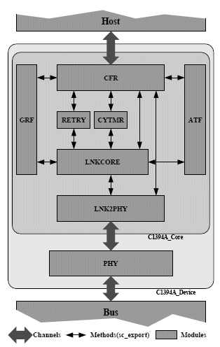
Figure 1. C1394A_TLM architecture overview
CFR submodule is responsible for :
- communication with host device,
- access to internal registers,
- writting data to transmit buffer (ATF),
- reading data from reception buffer (GRF),
- configuring and managing other modules of C1394A_Core.
Retry submodule implements single-phase retransmission protocol for retransmitting packets.
CyTmr submodule that is responsible for:
- generating Cycle Start packets
- updating internal timers in response for Cycle
- Start packet
- detecting Cycle Start Lost event
- maintaining Cycle_Timer register
ATF, GRF (CoreFIFO) - two hierarchical channels that provide extended FIFO functionality
LnkCore – part that implements most of model logic functions:
- forming and decomposing packets
- checking outgoing and incomming packets for their correctness (transaction code, CRC, etc.)
- acknowledge packets generation
- Cycle Master capability
- IRM node detection
- basic testing abilities
- data flow control
- interrupt control
- bus error control
Lnk2PHY- part acts as bidirectional interface between PHY and rest of model. Its tasks are:
- transmitting/receiving data to/from PHY
- providing access to PHY registers
- detecting and notifying model about bus events
- performing bus arbitration
Communication between submodules
Communication between submodules is done using sc_port – sc_export pair. Each submodule has corresponding interface with methods that are available to others and this interface is published using sc_export port. Another submodule can communicate with it via sc_port port (implementing same interface as exported by sc_export), that is bound directly (without using channels) to mentioned sc_export, as shown in the figure below :
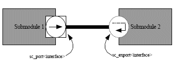
Figure 2. Communication between submodules
There is interface that defines set of methods that are implemented in submodule 2 and are accessible from submodule 1. They are published by second module via sc_export, which is linked with sc_port in first module.
Interaction with environment
C1394A_Core part of model uses blocking communication to exchange data with host device and PHY part:
- Standard SystemC request – response transport interface is used to handle CFR access requests from the host side, while interrupt handling is done by publishing sc_event reference. This interface enables direct interaction of the TLM model and the IEEE 1394 software stack to be run on the host processor in a native mode. Such approach enables software development and hardware / software co–design before the target processor architecture is actually chosen.
- Communication between C1394A_Core and PHY is done by custom channel consisting of seven FIFO buffers:
- two for sending / receiving data packets,
- two for sending / receiving acknowledge packets,
- one for sending PHY notifications to core (for example Status),
- one for sending Core notifications to PHY (for example Hold),
- one for sending Link Requests.
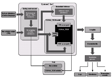
Figure 3. Simulation environment for software development
Since part of the PHY interface to the C1394A core interface works in half-duplex mode, some channels are synchronised using semaphore (to avoid data transfer conflicts). The interface between PHY and the core is designed with respect to IEEE 1394a-2000 standard to ease developing TLM to RTL transactors.
Testing environment for the model
In order to ease testing and verification process appropriate environment was developed - it consists of stimulus module that contains :
- Bison grammar analyser for parsing text files with packets definitions; all packets defined by IEEE 1394 standard are supported,
- Tcl script parser for processing script files containing bus activity together with core CFR access requests,
- Stimulus module for driving Host <-> Core interface - developed as SystemC module that contains Tcl script parser.
Embedded software development
C1394A_TLM model at PV abstraction level was designed to ease embedded software development and system verification process. Starting from pure- C++ algorithmic model, it was continuously refined by extending its functionality and adding SystemC communication / concurrency mechanisms. Along with C1394A_TLM development the software stack was being developed and almost from the beginning of their work software engineers took advantage of hardware-software co-simulation based on this model.
Since native compilation was used, high simulation speed could be achieved and software stack could be debugged using common software tools (like Visual C++). Testing environment based on TLM model is shown on figure 3. That speed allowed use of comprehensive test sets.
Not less important is bus scenario generation flexibility - there are no limits on events order declared in bus activity script, so there is possibility to develop non-standard sequences in order to check software behaviour in incorrect situations.
Since simulation and script execution can be stopped anytime, then resumed or restarted (which is much more difficult to achieve with software when already embedded in hardware), debugging and verification process was straightforward.
Once Instruction Set Simulator (ISS) for targeted processor is available in SystemC – it will be possible (with a limited speed sacrifice ) to check software operation with higher level of details.
Apart from benefits from availability of C1394A_TLM for software driver development, it will supply users’ with possibility to run software drivers along with their applications in the user’s system transaction level model.
C1394 software stack architecture
Using the approach described above a software driver supporting C1394a core has been developed. Layered architecture of this driver (shown in the figure 4) contains the following modules:
HdServices - hardware abstraction layer encapsulate the hardware access methods. Availability of TLM model was really crucial for effective debugging of this layer.
PacketServices – packet services layer works in interrupt mode, layer receives data from hardware buffers, creates data packets for future processing in a background mode.
PacketSwitch layer is responsible for packets recognition and passing them to higher layers.
TransCnt – transaction control layer is responsible for control and managing the data exchange process. This layer analyses the incoming packets and generates response (when it is needed) or passes packets to upper layers.
DevCnt layer functions creates and manage an array of handles, needed to which is necessary for communication of API layer with application layers in remote nodes. It provides access to remote nodes data descriptors (like device speed, transmission speed, EUI 64, status, physical id).
BusCnt – layer implements part of functionality required by the Bus Manager C1394 specification. The BusCnt layer contains functions for initiating node and bus. Layer prepares and holds the topology map and speed map.
IRMCnt - layer implements channel and bandwidth control registers, which can be used in the future to implement the full C1394 IRM functionality. This layer contains also functions responsible for “compare and swap” operation.
CycleCnt – When the local node becomes to a root node, then the CycleCnt layer activates the C1394 core Cycle Master which is responsible for creation of Cycle Start Packets on C1394 bus.
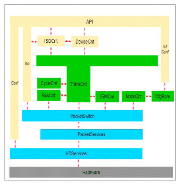
Figure 4. Architecture of the software stack supporting C1394a IP core
NodeCnt layer implements primary C1394 CSR registers architecture and provide access (read, write, lock) methods to these registers.
CfgRom layer implement the Config Rom registers, that describes the C1394 device plugged into the 1394 bus.
API – Application Program Interface layer between user application and C1394 soft stack. Major functions available in API implement:
- initialization / deinitialization of soft stack and core registers,
- transmission of asynchronous packets to remote nodes,
- receiveing of asynchronous packets from remote nodes
- configuration of isochronous connections between nodes,
- mapping of C1394 to application memory space.
TLM Model Development Directions
TLM model for PHY layer will be developed in the near future. This will extend capability of the model to support simulation of events in IEEE 1394 based networks. This improvement will enable possibility of simulation of the whole system consisting of several C1394A_TLM nodes (equipped with PHY component each), interacting with separate application (using software stack accessed by user application code), as shown in the figure 5.
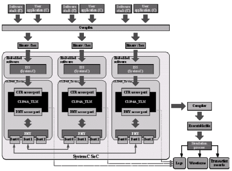
Figure 5. Simulation system setup for verification of multinode 1394a bus
As mentioned above PVT version of the model is under development. It will be interfaced in the future to the Instruction Set Simulator (ISS, under development, too) of C68000 microprocessor core (which was used in the hardware setup for final software testing).
Then it will be possible to cross–compile the software stack to the target architecture. The programmer will be able to debug the software interacting with C1394A_TLM by means of a debugger interfaced to this ISS (like Tasking Cross View or gdb version for targeted processor).
Conclusions
Transaction model of C1394A controller enabled effective debugging of the software stack thanks to model debugging features (especially easy access to each submodule state) and its speed of simulation which was dramatically increased when compared to VHDL-based C1394A RTL model. Possibility of running the hardware model and the software in a native C++ debugging environment made debugging much easier than any co-simulation setup could possibly offer.
Literature
1. IEEE Std 1394a–2000, © IEEE, published in 2000
2. C1394A Virtual Component Functional Specification, © Evatronix S.A. 2004 – 2005
3. OSCI Standard for SystemC TLM, available at http://www.systemc.org
4. Frank Ghenassia (Editor), Transaction-Level Modeling with SystemC : TLM Concepts and Applications for Embedded Systems, Springer, 2005
5. SystemC Language Reference Manual, ver, 2.1 © Open SystemC International, May 2005
6. David C. Black, Jack Donovan, SystemC: From the Ground Up, Kluwer Academic Publishers, 2004
7. Bjarn Stroustrup, The C++ Programming Language, Addison Wesley, 2000
Related Semiconductor IP
Related Articles
- Transaction Level Model of the USB On-The-Go controller IP core
- M31 on the Specification and Development of MIPI Physical Layer
- The Growing Imperative Of Hardware Security Assurance In IP And SoC Design
- Stop-For-Top IP model to replace One-Stop-Shop by 2025... and support the creation of successful Chiplet business
Latest Articles
- Lyra: A Hardware-Accelerated RISC-V Verification Framework with Generative Model-Based Processor Fuzzing
- Leveraging FPGAs for Homomorphic Matrix-Vector Multiplication in Oblivious Message Retrieval
- Extending and Accelerating Inner Product Masking with Fault Detection via Instruction Set Extension
- ioPUF+: A PUF Based on I/O Pull-Up/Down Resistors for Secret Key Generation in IoT Nodes
- In-Situ Encryption of Single-Transistor Nonvolatile Memories without Density Loss