UA Link PCS customizations from 800GBASE-R Ethernet PCS Clause 172

Introduction
Ultra Accelerator Link (UA Link) standard has been specified to enable the creation of systems comprised of multiple nodes targeting AI applications. The UA Link Protocol and interfaces are defined to support low latency Accelerator to Accelerator communication across these system nodes using direct read, write and atomic transactions without the need to engage the host CPU int the process. The whole protocol stack for UA Link is composed of the Transaction Layer (TL), Data Link (DL), Reconciliation Sublayer (RS), Physical Coding Sublayer (PCS), and Physical Medium Attachment Interface (PMA), and while the PMA is identical to the one used for IEEE 802.3 with the exception of the option for skipping the codeword delay for interleaving, the PCS has undergone some further optimizations that are described in this article.
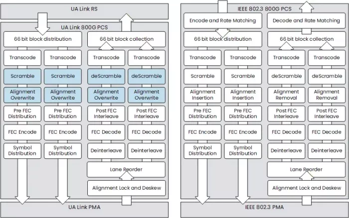
Figure 1. High-level PCS flow diagrams created from concepts derived from the IEEE 802.3DJ and UA Link 2.0 specifications
The two presented diagrams are almost identical, with the changes in the UA Link specifications colored in the diagram on the left. These would be the Scrambling/Descrambling blocks as well as the Alignment Overwrite blocks in both the Transmit and Receive direction.
The UA Link specification for the PCS references the Ethernet specification directly in many of its sections i.e., the UA Link 7.6.1.2 Transcoder subsection reads: “See 802.3 clause 172.2.4.3.” Indicating the UA Link PCS operates in a similar fashion to the 802.3 Clause 172 PCS allowing for similar design architecture and reuse opportunities. This article will explore the differences between the two specifications outlining changes and optimizations introduce to support the Ultra Accelerator Link.
Alignment Overwrite vs Alignment Insert
In comparison to the 802.3 Ethernet 800GBASE-R PCS the UA Link PCS does not insert the Alignment Marker sequence in between the data stream, but the necessary slots are pre-reserved by the Reconciliation Sublayer and later only overwritten by the PCS. There are eight 256B/257B blocks that get overwritten in each of the flows. The alignment marker encodings are identical to those found in the 802.3 clause 172.2.4.6 only the mechanisms by which they are introduced into the data stream and the effects on data flow change in UA Link.
In the receive direction the Flit Code sequence will contain the alignment markers (AM) inserted by the TX, and if Alignment Lock is achieved the sequence will be converted to an AM Flit Code Sequence. This sequence is split between the two flows with odd and even indexed 64B66B blocks. On each flow the AM Flit code sequence will be identical with a fixed data pattern. The converted AM Flit Code sequence is then passed the Descrambler.
Differences in the FEC implementation
The 802.3 specification defines 4-way interleave of 200GBASE-KR1 lane, with a 2-way interleaving occurring in the PCS via the 10bit distribution across 2 FEC encoders and another 2-way interleave occurring in the PMA by the means of delaying odd symbols by two code words. Distributing potential bit error bursts across data from 2 different time periods and across 2 parallel FEC decoders allows for a RS FEC 544,514 implementation which normally can correct 15 symbols of error burst to now correct up to 60 symbols. This however has additional implications with added latency and resource utilization on the design.
To optimize this UA link proposes 2-way and even 1-way interleaving solutions. The reach of the UA link to accelerators is reduced compared to regular Ethernet 800G solutions and the increase in RS FEC strength might not be always required. With the 2-way interleave the PMA will no longer perform the two codeword delay. In the 1-way interleave not only the PMA delay functions are circumvented but also the PCS will no longer perform the 10-bit symbol distribution to two FEC encoders. In such a case only a single FEC encoder is used.
In Conclusion
Even though the modifications to the PCS are not significant in terms of scrambling and alignment markers, the advanced FEC interleave modes can pose a challenge in implementing compliant UA Link solutions. Luckily Chip Interfaces engineers with their long history in implementing high speed Ethernet solutions and RS FEC enabled PCS blocks across multiple standards, have prepared a standard compliant solution ready to be integrated into your custom UA Link designs. The PCS additionally supports Ultra Ethernet Links and is a great fit for the modern Data Center deployments.
Related Semiconductor IP
- UA Link TL IP core
- UA Link DL IP core
- UALink PCS IP Core
- UALink Controller
- Simulation VIP for UALink
Related Blogs
- From IBM Mainframes to Wintel PCs to Apple iPhones: 70% is the Magic Number
- HP, Palm, tablets, PCs, smartphones
- 400G Task Force, 100G Backplane Project and Other Highlights from IEEE 802.3 Ethernet Standards Meeting
- Highlights from Recent IEEE 802.3 Ethernet Standards Meeting
Latest Blogs
- Area, Pipelining, Integration: A Comparison of SHA-2 and SHA-3 for embedded Systems.
- Why Your Next Smartphone Needs Micro-Cooling
- Teaching AI Agents to Speak Hardware
- SOCAMM: Modernizing Data Center Memory with LPDDR6/5X
- Bridging the Gap: Why eFPGA Integration is a Managed Reality, Not a Schedule Risk