Understanding Interface Analog-to-Digital Converters (ADCs) with DataStorm DAQ FPGA
By Mangesh Lad, Dibyajyoti Samal (eInfochips)
May 30, 2022
Understanding Interface Analog-to-Digital Converters (ADCs) with DataStorm DAQ FPGA
Introduction:
Analog-to-Digital Converter (ADC) is used for the conversion of analog signals such as voltage to digital form so that they can be read and processed by a microcontroller or microprocessor. The user program must start the ADC conversion process, and it takes several microseconds for the conversion to complete.
ADC converters are very useful for controlling and monitoring applications such as temperature sensors, pressure sensors, and force sensors to monitor analog output voltages.
We propose the implementation of analog signals into digital signals and data communication between the ADC and FPGA (Field Programmable Gate Array). For working on the ADC, we have used the “DataStorm DAQ” FPGA board. Designers can use any type of FPGA.
Applications:
- Automated test equipment
- Machine automation
- Medical equipment
- Communication
- Aerospace and defense
- Data acquisition system
Let’s try to understand the technical aspects of this article. Firstly, we have provided the information about hardware implementation and later, we have given the Software (Application) implementation. For more reference, visit here.
Architecture Used for Communication With the ADC
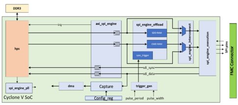
We will understand the process and the workflow for communication of the ADC with the FPGA. The FPGA serves as the digital host for the ADCs. It also consists of various interfaces and modules for configuration, control, and conversion data processing.
Interfaces Used
- SPI Engine module
- DMA module
- UP_AXI Interface module
Figure 1: A snippet of the architecture for the ADC board and the FPGA Board is shown above.
SPI Engine
In this design, we have used the SPI protocol for communication between the FPGA (Field Programmable Gate Arrays) and the ADC (analog-to-digital converter) as it is synchronous serial communication interface specification used for short-distance communication, primarily in embedded systems.
The SPI Engine is flexible and has a powerful SPI controller framework. The SPI Engine comprises multiple sub-modules that can communicate over well-defined interfaces. It allows high flexibility and re-usability, while at the same time staying highly customizable and extensible.
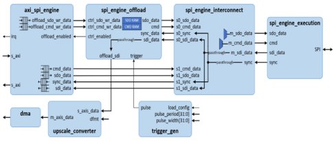
The following sub-modules are used while transferring address and data between the master and the slave:
Sub-modules
- SPI Engine Execution Module
- SPI Engine Interconnect Module
- SPI Engine Offload Module
- AXI SPI Engine Module
Figure 2: A snippet of the SPI Architecture for AD7768-1 ADC board for the FPGA is shown above.
1) SPI Engine Execution Module:
The SPI Engine Execution peripheral is the heart of the SPI Engine framework. The SPI Engine Execution is responsible for handling the SPI Engine control and translates it into an SPI bus transaction.
2) SPI Engine Interconnect Module:
The SPI Engine Interconnect module allows connecting a single SPI Engine Control Interface master to a multiple SPI Engine Control Interface slave. The SPI Engine Interconnect module enables multiple command stream generators to connect to a single SPI Engine Execution module and consequentially gives them access to the same SPI bus. The interconnect modules arbitrate properly between different command streams.
The SPI Engine Offload peripheral enables storing the SPI Engine command and the data stream in a RAM (Random Access Memory) or ROM (Read Only Memory) module. The command stream is executed when the trigger signal is affirmed. This allows execution of the SPI transaction with a short delay in reaction to the event.
The AXI SPI Engine module allows asynchronous interrupt-driven memory-mapped access to an SPI Engine Control Interface. This Module also support memory-mapped access to one or more offload and change its content at runtime.
B) DMA (Direct Memory Access)
DMA is an internal buffer used for storing data from the source interface before it is transferred to the destination. The purpose of the DMA is to even out the mismatch between the source and the destination.
There is an instance of the DMA controller in design, which operates at a data width of n-bits for N bit resolution ADC.
The DMA is a general-purpose DMA controller intended to be used to transfer data between the system memory and other peripheral like converters.
C) UP_AXI Interface Module
All FPGA cores contains multiple AXI register module. To avoid complicated interconnection inside module, using up_axi module the AXI memory-mapped interface converted into microprocessor interface or up_axi interface .
This interface has independent read and write channels, and each channel contains address bus, data bus, request and acknowledgement control signals.
Implementation of Software
Once the HDL has been developed with the necessary external interfaces, the Datastorm DAQ can use them to physically connect with any of the secondary (ADC) data acquisition modules. Now, even though the HDL starts receiving the data during bootup, it will not be able to automatically dump the processed data into the memory until some important sections of the systems have been initialized.
The Linux Software Stack
This is achieved by using the Linux operating system components like:
- The Device Trees
- The Device Drivers
- Linux Software Applications
The Device Tree
When a data acquisition module is connected to the Datastorm DAQ board, the Linux operating system utilizes a Device Tree Source (DTS) file specific to the secondary (ADC) board to initialize the relevant drivers during bootup. The DTS file provides a description of every external interface as well as all hardware present on board readable by Linux so that it does not need to hard code details of the machine every time it boots.
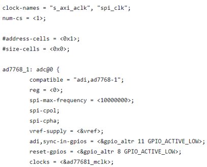
Figure 4: A snippet of the DTS file for AD7768-1 ADC secondary (ADC) board for the Datastorm DAQ (FPGA) is shown above.
The Device Driver
While the device tree provides only the reference description of the hardware to the OS, the device driver is the software that uses those descriptions to directly manage the physical hardware via the HDL interfaces. The Datastorm DAQ uses four main drivers for device management and data acquisition.
- I/O Drivers
- DMA Controller (dma_APIs)
- SPI Engine (spi_engine)
- IIO device driver (iio_dev)
I/O Drivers
Input and Output (I/O) ports for any hardware are the lowest level of direct communication. I/O ports are highly architecture-dependent and hence to unify this, the Linux kernel uses memory-mapped I/O registers. This essentially maps the physical addresses to the Linux virtual memory addresses and hides the details from different drivers to ease portability. The I/O functionalities are accessed by including the linux/io.h header file that can then be used locally by the drivers.
DMA Controller
Direct Memory Access (DMA) Controller allows peripherals to access the main system memory independently without going through the CPU’s virtual memory addressing system.
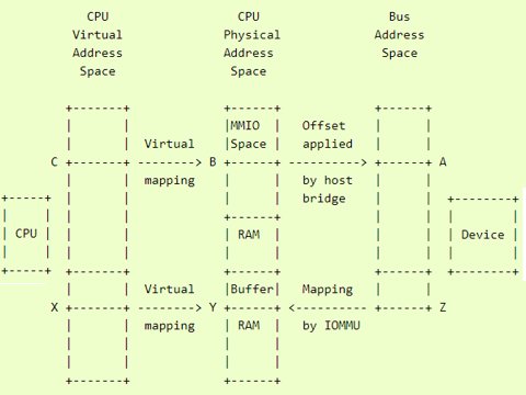
Figure 5: Dynamic DMA mapping Guide — The Linux Kernel documentation
The driver first sets up a buffer by allocating some memory. The driver gives the system a virtual address X that is mapped to a physical address in the system memory Y. The device can then be sent to the DMA directly (or via an IOMMU hardware) to the physical address Y. This allows the buffer to access the data from the DMA address Z, which is dumped by the data acquisition module and can be used by the memory for further processing.
SPI Engine
SPI drivers are broadly categorized into two types:
- Controller Drivers: These drivers abstract the actual controller hardware and interact directly with the hardware registers.
- Protocol Drivers: These drivers use the controller driver to pass messages onto the secondary device on the other side of the SPI link.
The Datastorm DAQ platform uses either SPI or SPI Engine controller drivers to communicate with the secondary data acquisition module, which is in turn initialized as a protocol driver. This enables the data acquisition process as explained in the HDL section above.
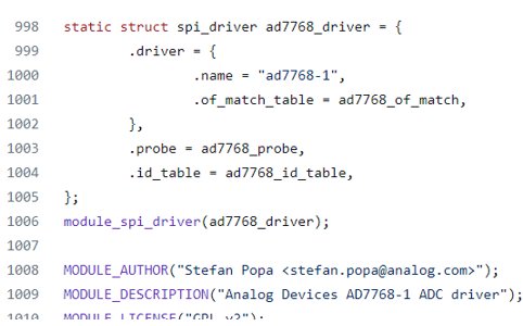
Figure 6: A snippet for the AD7768-1 secondary ADC board defined as a protocol driver is shown above.
IIO Drivers
Industrial I/O (IIO) Drivers allow hardware support for those devices that exist in between the realm of strictly monitoring and strictly input-based devices. These include devices such as Analog-to-Digital Converters (ADCs), Digital-to-Analog Converters (DACs), Inertial Measurement Units (IMUs), gyroscopes, and other sensors.
These drivers usually register themselves as either I2C or SPI drivers, but to be able to acquire data from them, a buffer is necessary by allocating some memory. This buffer is then filled with data by using either SPI controller-based triggers (iio_triggered_buffer_alloc) or by using SPI Engine controller-based DMA triggers (iio_dmaengine_buffer_alloc).
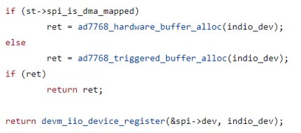
Figure 7: A snippet for the AD7768 ADC board defined as an IIO Driver is shown above.
The incoming data from the data acquisition module is then made available to the driver which allows easier access to the IIO device via different user applications. The Datastorm DAQ provides support for such IIO-based data acquisition drivers as ADCs and DACs.
The Software Applications
In the last segment, we emphasized the fact that the IIO device is registered as an SPI device and that the incoming data is private to the IIO driver. This means that the data coming from the IIO device cannot be read and used directly by the user-level applications. But to be able to utilize the strengths of data acquisition platforms, we need to be able to access that data from the OS to be able to utilize that for further analysis. Here, the LibIIO middleware comes in.
LibIIO abstracts both the backend required for communication as well as data transfer with the Linux driver. It has many high-level APIs that can be utilized by different software to access the data that was captured privately by the IIO driver.
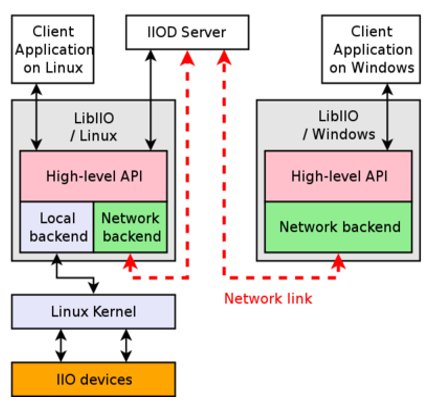
Figure 8: What is libiio? [Analog Devices Wiki]
LibIIO can “stream” the incoming data either locally on the board itself or remotely over computers on a network. IIOD Server (above figure) is one such application that uses LibIIO that allows it to receive the same data that we see on the board and send it to other servers on different computers over the same local area network (LAN). Other client applications that can use both local and network backends include C (libiio), Python (pyadi-iio), and MATLAB IIOStream applications.
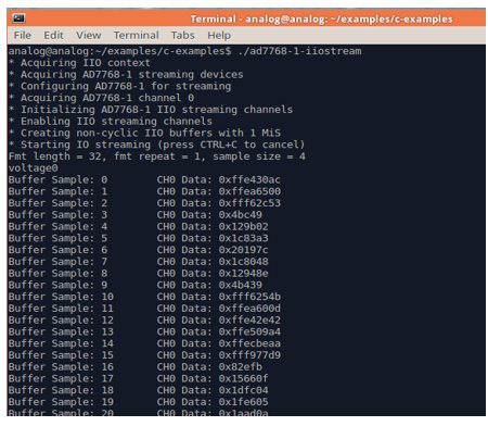
Figure 9: A snippet of the C IIOStream example for the AD7768-1 ADC running locally on the primary board.
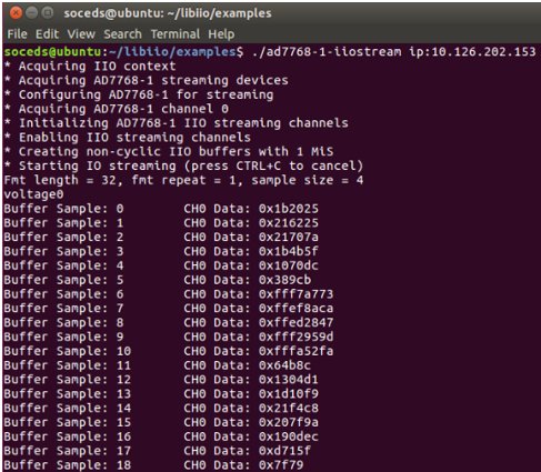
Figure 10: A snippet of the C IIOStream example for the AD7768-1 ADC running remotely on a network computer connected by an IP address.
no-OS Bare-metal Development
The Datastorm DAQ board does allow major operating systems like Linux to run on it, but many a time developers prefer to use bare-metal programs that can be directly loaded onto the memory. This is referred to as a no-OS driver and application development.
The no-OS drivers follow a similar structure in terms of operation to that of the Linux drivers but with a core difference in the removal of the IIO drivers, LibIIO, and IIOD Servers. Due to a lack of an OS, there are no user-level applications that can be run, and instead, the data is directly accessed over any other interface on the board like serial ports.
no-OS applications are typically very fast in execution as they load virtually instantly, and are hence the preferred mode of operation in many time-sensitive situations, where the facility for an entire operating system is not necessary.
Conclusion:
The detailed implementation is done on different types of ADCs and the summary of various features is presented. The analysis and trend prove the frequent use of the ADC due to its highly efficient speed performance and scaling process.
eInfochips’s hardware and software learning offerings help organizations build highly customized solutions running on any FPGA board. We also help companies integrate the FPGA and ADC architecture with HDL (Hardware Descriptive Language) & Software (Linux driver and NO-os). We deliver the utmost customer satisfaction and ensure that our partners meet their business goals. To know more about our services, contact our experts.
About the Authors
 | Mangesh Lad is an engineer at eInfochips with a primary focus on embedded FPGA development, verification, and validation. He has 1.5 years of product engineering experience. Mangesh holds a bachelor’s degree in Electronic Engineering from Shivaji University and Master of Technology from College of Engineering, Pune. |
 | Dibyajyoti Samal is an engineer at eInfochips primarily focusing on embedded software development. Joined as a fresher, he currently has 1.5 years of experience at eInfochips. Dibyajyoti has graduated as an Electronics and Telecommunication Engineer from Pune University. In free time, he likes to make music and play video games. |
Related Semiconductor IP
- ADC
- Compact, low-power, 8bit ADC on GF 22nm FDX
- 7-Channel 22-Bit 9.6KSPS ADC with Internal Reference - SMIC 40nm
- 24-Bit Stereo Audio ADC, SNR>95dB - SMIC 110nm
- 24-Bit Stereo Audio Codec ADC, ADC SNR>95dB, DAC SNR>100dB - SMIC 55nm
Related White Papers
- Modeling high-speed analog-to-digital converters
- How to implement *All-Digital* analog-to-digital converters in FPGAs and ASICs
- Understanding SD, SDIO and MMC Interface
- Stellamar's all-digital, fully-synthesizable, analog-to-digital converters for Microsemi FPGAs
Latest White Papers
- Ramping Up Open-Source RISC-V Cores: Assessing the Energy Efficiency of Superscalar, Out-of-Order Execution
- Transition Fixes in 3nm Multi-Voltage SoC Design
- CXL Topology-Aware and Expander-Driven Prefetching: Unlocking SSD Performance
- Breaking the Memory Bandwidth Boundary. GDDR7 IP Design Challenges & Solutions
- Automating NoC Design to Tackle Rising SoC Complexity
