Smart Wave Dump - A smart way to generate waveforms
By Navdeep Patel, Nikunj Naliyapara (eInfochips, an Arrow Company)
1- Introduction
As an engineer, be it design or verification, more than half of our time is spent in debugging and analysis. One of the most common and basic approach to that is using the waveform that shows the behavior of the signals. It is very likely that we are aware about how to dump such waveforms and observe the behavior of the signals we are interested in, but majority of the time, we also dump much more than what we need. We can ignore the signals that are not of interest to us in the recording, but here we should note that if we do not generate the waves properly then, we may face some disadvantages or challenges compared to ‘Smart Wave Dump (SWD)’.
eInfochips’ SWD provides several advantages over traditional waveform generation methods. Some of the advantages are faster simulation, smaller waveform files, faster execution of waveform analyzer tool, etc.
One of the main advantages of SWD is, it is tool and project agnostic. It supports Cadence, Synopsys and Mentor Graphics tools and it is reusable across different projects. Therefore, SWD is a generic solution to generate waveforms. Here at eInfochips, we have used SWD in multiple projects with different tools.
SWD supports features like, save the waveform database as per scope or hierarchy, dumping the waves in specific time range, store delta cycle values or value change sequence in the waveform database and many more. Details about the same will be provided in upcoming sections.
So, let us look further into next sections and understand more about SWD.
2- About SWD
SWD comprises system tasks from SystemVerilog LRM and user guides of various simulation tools. Therefore, user just needs to include the SWD package in the Testbench and then can use it with help of a set of predefined command line switches. Such predefined command line switches are used to control the waveform generation for various nodes (in/out signals, memories, objects declared in task and function scopes, etc.), various scopes (hierarchical instantiations) and other supported set of features.
SWD supports below mentioned features. We will look into more details for each of those in next section.
- Scope / hierarchical dumping
- Memory (multi-dimensional arrays) dumping
- Delta cycle values dumping
- Waveform database storage for given simulation time
- Split Waveform dump file
- Limit maximum file size for the waveform file
- Compression of waveform file
- VCD dumping
From above listed features, SWD is reusable across multiple projects for almost all features apart from scope / hierarchical dumping. Because, with different project there can be different hierarchy so, based on individual’s requirement user need to update the hierarchical paths for scope dumping. Upcoming sections have more detail on scope / hierarchical dumping.
3- Features Supported
SWD supports various features to generate the waveform database. Each feature has its own command line switch. User can use more than one feature at a time by using multiple command line switches. User can use various features of SWD package as per requirement and does not need to worry about various tool specific switches.
Supported features are as below:
- Enable dumping: This is normal dumping, to enable the creation of waveform database. By default every signal of each hierarchy are stored in the database for full simulation time. SWD package already provides such legacy-dumping feature, so, user does not need to add the same separately. However, users should consider that using this feature could result in usage of more disk space and more simulation time compare to using various features of SWD as per requirement.
- Scope dumping: This is a kind of partial dumping by selecting set of interested hierarchies. User can generate the waveforms by controlling the dump scope. This is one of the biggest features of SWD and requires separate attention; so, it is discussed in detail in next section. User can control the dump scope as per various scope_profile_name in Scope Control Task (Refer Section 4). Scope dumping helps to improve the simulation speed and to save disk space.
- Scope dumping from a text file: User can also take advantage of Scope dumping by creating a text file. This text file should contain the hierarchy and scope level information. One of the tool, Visualizer from Mentor Graphics, supports scope dumping feature with text file. It is recommended to use tool specific user guide to get more details on format of text file. Once this text file is developed, user can use it directly as SWD package supports Scope dumping from text file.
- Memory dumping: This feature is helpful to store multidimensional arrays or memory. By default, the waveform database does not store multidimensional arrays or memory. Using this feature can result in slower simulation and more disk space consumption than non-memory dumping. So, it is recommended to use this feature only when it is a requirement. One of the practical application of this feature is to view and debug pre-loaded / backdoor loaded memory content in waveform viewer tool.
- Delta cycle values dumping: This feature is helpful to store multiple value changes or sequence of value changes for an object during one simulation time. This feature is costly for simulation speed and disk space, as using it can result in slower simulation and more disk space consumption. So, by default, delta cycle values does not get stored in waveform database. A signal can have glitches because of SV event regions or race conditions, so, this feature is important and useful to debug glitches in any such signal and to find out if such glitches are causing some unintentional behavior. For e.g. if a signal with glitches is used in sensitivity of always block then such always block might start the execution unintentionally.
- Dumping within given time range: This feature is useful when user wants to start and stop the waveform dump as per simulation time. User must provide start time and end time to use this feature. By default, the waveform database will be generated for full simulation time. The SWD package provides an error, if start time is greater than end time. This feature can be helpful to improve the simulation speed and to save disk space. This feature can be helpful in Gate Level Simulations (GLS), as in GLS wave database size can be very large so, using this feature to dump within specific time range, user can save good amount of disk space and decrease the simulation time.
- Split Waveform database: By default, there is no limit on the size of a database. As a database for a large simulation can be very big, user might want to break up the signal transition information into multiple files. Breaking up a large database file into incremental files can make the simulation results more manageable. User can open just one incremental database file, or any subset of the files, in waveform viewer so that user can view the waveforms for the time range/s corresponding to that file or set of files.
This can improve viewer performance and memory usage. It can also be used to ensure that database files are kept under some specified size (for example, 1 GB), and files corresponding to uninteresting time ranges can be deleted later to save disk space. To use this feature, user can provide database size in MB as the split size for a single database. When current database size reaches the specified split size, a new database will be generated. - Maximum number of waveform databases: While using the above mentioned feature “Split Waveform database”, multiple databases will be generated. By default, the simulator can create and store as many databases as needed but if user wants to limit the number of such split databases then it can be done with usage of this feature. This feature will only be used with “Split Waveform database” feature.
- Maximum file size for the waveform file: This feature can be helpful to limit the maximum size of waveform database. User can provide maximum size in bytes and the database size will not exceed the specified limit. This could be helpful if disk space is limited or user wants to control the database size. The simulator will maintain the size limit of database by discarding the earliest recorded values as new values are saved so, the waveform database will always contains the most recent values. The discarded values will be shown as unknown value (x). This feature is useful if disk space is limited and/or database size is going to be very large however, continuous analysis of recorded signals is required.
- Compression of waveform file: This feature can be helpful in reducing the size of waveform database by compressing it. This can be useful to save database for future reference or to share across multiple users. However, using this feature might result in more simulation time and memory usage.
- VCD format dumping: This feature can be helpful to create the value change dump (VCD) file. Being part of language standard, VCD file format provides several advantages, for e.g. it can be used across different tools. One of the application of VCD files is that, power analysis tools takes VCD files as input along with netlist and other necessary files. However, user should be aware that VCD file size can be quite large based on simulation compare to tool specific database.
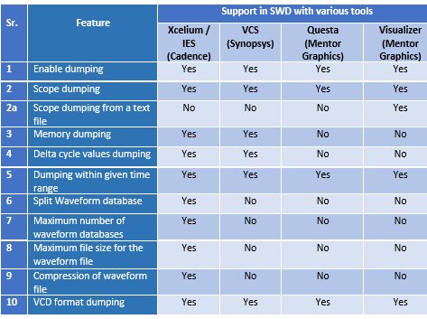
SWD package can be used with multiple EDA tools but it is possible that support for mentioned features will vary as per tool vendor. So based on that, SWD supports the listed features for various tools as per below Table 1:

Table 1: SWD features support with different tools
In above Table 1,
“Yes” means SWD package supports that feature with given tool,
“No” means SWD package currently does not support that feature with given tool but the tool may or may not support the feature.
4- Scope / hierarchical dumping of SWD
Let us take an example to understand better scope / hierarchical dumping feature of SWD. A chip has multiple IPs/sub blocks and it might be possible that those IPs/blocks are divided across multiple engineers. Now, while debugging, we would be more interested in the assigned block and other blocks with which it interacts and so is the case for waveforms. Let us say we dump only the signals for which we are interested about and skip others. This can be achieved using scope dumping feature of SWD.
User can use Scope dumping feature to dump signals selectively from design and/or test-bench scopes.
There is one Scope Control Task in the SWD package. This task consists the list of scope dumping items with details of hierarchical paths and scope level. At starting of any new project, user need to do one time update for the hierarchical paths to support scope dumping. Then SWD package can be used with different tools throughout the project. Even this updating process is not required if user is using the SWD package for any derivative project.
Scope Control Task:
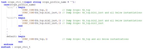
To understand more about the Scope Control task, please look into below Figure 1. There is a sample code of Scope Control Task of the SWD package.

Figure 1: Sample code of Scope Control Task
Scope Control Task has a macro “DUMP_COMP” that contains the tool specific or SV system tasks and logic that makes the SWD package generic and reusable across multiple tools. This macro takes two arguments, first one is the instance name (scope or hierarchy) and second one is the scope level.
There are two major supports provided for scope level,
- If the scope level is ‘1’ then, the simulator will record inputs, outputs and inouts value changes in the specified scope/instance only.
- If the scope level is ‘0’ then, the simulator will record all signals' value changes in the specified scope/instance and in all instantiations below the specified scope/instance.
For example,
- `DUMP_COMP(tb_top,1)
- tb_top is the scope and ‘1’ indicates that inputs, outputs and inouts value changes will be recorded for tb_top instance.
- `DUMP_COMP(tb_top.blk2_inst,0)
- tb_top.blk2_inst is the scope and ‘0’ indicates that all signals’ value changes will be recorded for tb_top.blk2_inst instance and all instantiations below it.
Scope Control Task have one input argument, scope_profile_name. User can use this scope_profile_name in command line argument while running the testcase to specify which signals / hierarchies needs to be recorded for a specific testcase. Therefore, from Figure 1, if user uses scope_profile_name as “blk1” then, inputs, outputs and inouts value changes will be recorded for tb_top instance and, all signals’ value changes will be recorded for tb_top.blk_inst1 instance and all instantiations below tb_top.blk1_inst.
User can update this Scope Control Task by adding or removing or updating scope_profile_name cases inside the case statement and create as many as scope profiles required, along with various dumping scope within one scope profile.
This is highly recommended and very useful feature of SWD.
5- Flow to use SWD
Below Figure 2, explains flow for SWD usage:

Figure 2: Flow to use SWD
- Include the SWD package
- As mentioned earlier, SWD comprises of SystemVerilog and tool specific system tasks. Therefore, user will have to include the SWD package in the Testbench.
- Update the Scope Control Task
- As discussed, Scope Control Task in the SWD package consists the list of scope dumping items with details of hierarchical paths and scope level. Therefore, at the beginning of any new project, user has to do a one-time update for the hierarchical paths to support scope dumping.
- This update is required only to support scope dumping, otherwise this update can be skipped and rest of features of SWD can be reused without any update.
- Run testcases with command line argument/s (CLA) as per requirement
- As SWD supports various features, user has to provide specific command line switch to use that specific feature as per requirement.
6- Tcl script based approach for SWD
Another approach for SWD is Tcl (Tool command language) based. If tool supports Tcl files for waveform generation then this approach can be used. Here, SWD package will contains Tcl scripts with procedures and system tasks from tool manuals.
This Tcl script based approach for SWD, also supports various features discussed in previous sections. Therefore, similarly, user can use the SWD Tcl package while running any testcase or regression along with appropriate command line switches.
For Scope / hierarchical dumping, there is one scope control procedure in the SWD package. This procedure consists the list of scope dumping items with details of hierarchical paths and scope level. Here, user can specify scope level (depth from specified scope/instance) as per requirement, which can be ‘0’, ‘1’,’2’, etc.
In below Figure 3, there is a sample code of Scope Control Procedure of the SWD Tcl package. A “set_scope_profile” procedure can be there to handle which signals / hierarchies needs to be recorded.

Figure 3: Sample code of scope control procedure in SWD Tcl package
User can update this Scope Control Procedure by adding or removing or updating ‘set_scope_profile’ and create as many scope profiles as required, along with various dumping scope within one scope profile.
One of the advantage of Tcl based approach is, it is compilation agnostic so, Tcl file can be updated and directly used with already compiled database snapshot in case required.
7- Advantages
Some of the main advantages of SWD are as below:
- Helps in generating waveform database as per requirement
- Improves simulation speed, as waveform database is generated as per interest
- With proper usage of wave dumping, waveform file consumes lesser storage memory and saves disk space
- Improves viewer performance and memory usage
- Faster execution of analyzer tool helps to improve engineer’s productivity with faster debug
- Helps to generate manageable and maintainable waveform databases
- Improves productivity of the project
- One solution for multiple requirements on waveform generation
- Tcl based approach is compilation agnostic
8- Example to demonstrate advantages of SWD
As mentioned, SWD can be helpful to improve simulation speed and save disk space. To demonstrate that, we have taken an example of Xcelium simulator from Cadence and tried some features of SWD.
This example is from one of the projects, which had around 15 digital blocks/IPs with reasonable complexities. We ran a sample test with below mentioned categories:
- Full dump: Dumping every hierarchy for full simulation time (Simulation time of the sample testcase is ~180ms).
- Scope dump: Dumping one of the main controlling block along with three other blocks with which it interacts and its corresponding testbench parts (interfaces, assertions, etc.) for full simulation time.
- Time range dump: Dumping every hierarchy for selective (set of interested) simulation time, we have taken start and end simulation time as 50ms and 100ms respectively.
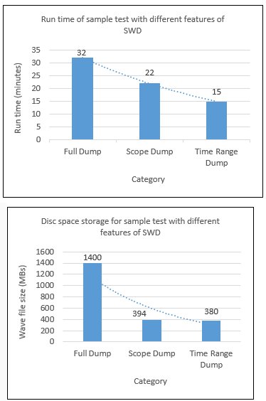
Below Figures 4 & 5, shows simulation run time and waveform file (database) size for above listed categories:

Figure 4: Run time and disk space storage for sample test with different features of SWD
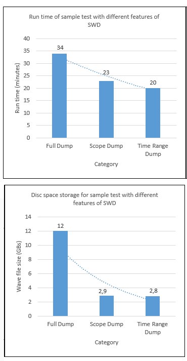
The same three categories with delta cycle values dumping for the same sample test, please see below Figure 5 for the outcome:

Figure 5: Run time and disk space storage for sample test with different features of SWD and delta cycle dump
It is clear that with Scope Dump and Time Range Dump features of SWD, one can improve simulation speed (approx. 30% to 50% lesser simulation time) and save good amount of disk space.
9- Conclusion
We have seen that using SWD, how user can generate the waves and gain advantages like, faster simulation, better viewer performance, save the disk space, etc. and improve the overall project efficiency.
Using SWD, user can utilize time and disk space efficiently. Since SWD provide generic solution across multiple EDA tools, user need not to bother about different EDA tools specific switches and commands and can use SWD to gain various advantages as discussed. Efficiency plays major role and SWD helps to improve it. eInfochips, an Arrow company, is a leading global provider of product engineering and semiconductor design services. With over 500+ products developed and 40M deployments in 140 countries, eInfochips continues to fuel technological innovations in multiple verticals. For more information connect with eInfochips today.”
References:
- IEEE Standard for System Verilog – 1800-2017
- Tool reference manuals from Cadence, Synopsys and Mentor Graphics
Authors:
Navdeep Patel: Navdeep Patel is working as a Senior ASIC Verification Engineer at eInfochips, an Arrow Company.
Nikunj Naliyapara: Nikunj Naliyapara is working as a Senior ASIC Verification Engineer at eInfochips, an Arrow Company.
Related Semiconductor IP
- NPU IP Core for Mobile
- NPU IP Core for Edge
- Specialized Video Processing NPU IP
- HYPERBUS™ Memory Controller
- AV1 Video Encoder IP
Related White Papers
- Securing a 4G-connected Smart Meter Gateway with CHERI
- Smart way to memory controller verification: Synopsys Memory VIP
- Paving the way for the next generation of audio codec for True Wireless Stereo (TWS) applications - PART 5 : Cutting time to market in a safe and timely manner
- Vital Ways to Prevent a Cyberattack
Latest White Papers
- Ramping Up Open-Source RISC-V Cores: Assessing the Energy Efficiency of Superscalar, Out-of-Order Execution
- Transition Fixes in 3nm Multi-Voltage SoC Design
- CXL Topology-Aware and Expander-Driven Prefetching: Unlocking SSD Performance
- Breaking the Memory Bandwidth Boundary. GDDR7 IP Design Challenges & Solutions
- Automating NoC Design to Tackle Rising SoC Complexity