Analog IP for UMC
Welcome to the ultimate
Analog IP
for
UMC
hub! Explore our vast directory of
Analog IP
for
UMC
All offers in
Analog IP
for
UMC
Filter
Compare
1,207
Analog IP
for
UMC
from
20
vendors
(1
-
10)
-
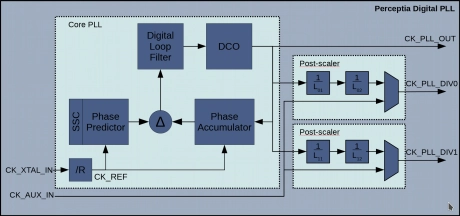
All Digital Fractional-N PLL for Performance Computing in UMC 40LP
- Fractional multiplication with frequency up to 4GHz
- Low jitter (< 10ps RMS)
- Small size (< 0.01 sq mm)
- Low Power (< 5mW)
-
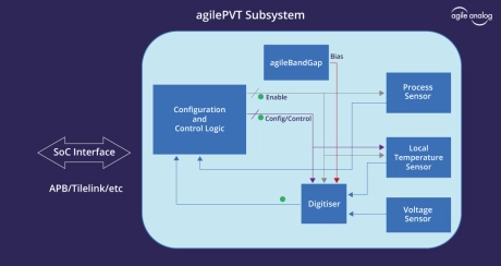
PVT Sensor Subsystem
- Start-up time: Typ 20us
- Current consumption: Max 25uA
- Industry standard digital interface
- Fully integrated macro
- Standard AMBA APB interface
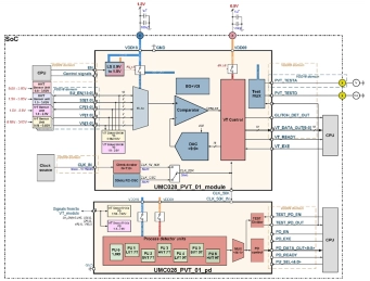
-
Process/Voltage/Temperature Sensor (Supply voltage 1.8V/0.9V)
- UMC 28nm HPC+ technology
- Temperature measurement range -40°C ÷ +125°C
- Core and IO Voltage measurement range: 0.58V÷0.92V, 1.0V÷2.0V, 1.5V÷3.63V and 0.8÷3.63V
- High accuracy temperature and voltage measurements
-
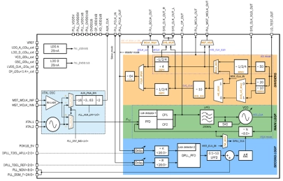
2.26GHz/2.46GHz Fractional-N LC Phase-Locked Loop with oscillator
- 180XFAB_PLL_01 uses 2.25792GHz/2.4576GHz Phase locked loop frequency synthesizer for clock generation.
- It consists of the following main sub-blocks: reference oscillator; main PLL loop: Fractional-N PLL and VCO blocks; secondary digital PLL loop: synchronization subsystem; dividers block: clock generation/delivery subsystem; voltage stabilizers.
- High frequency synthesis is needed for both phase noise performance and ultra-fine frequency tuning step.
-
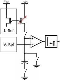
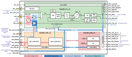
10MHz to 50MHz fractional-N PLL synthesizer
- UMC 22nm ULP technology
- 1.8V IO power supply
- Double 0.8/1.0V Core power supply
- Embedded low noise bias
-
All Digital Fractional-N RF Frequency Synthesizer PLL in UMC 40LP
- Fractional Multiplication with frequencies up to 8GHz
- Extremely low jitter (< 300fs RMS)
- Small size (< 0.05 sq mm)
- Low Power (< 15mW)

-
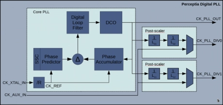
General Purpose All Digital Fractional-N PLL in UMC 40LP
- Low jitter (< 18ps RMS)
- Small size (< 0.01 sq mm)
- Low Power (< 3.5mW)
- Support for multi-PLL systems
-
General Purpose All Digital Fractional-N PLL in TSMC N6/N7
- Low jitter (< 18ps RMS)
- Small size (< 0.01 sq mm)
- Low Power (< 3.5mW)
- Support for multi-PLL systems

-
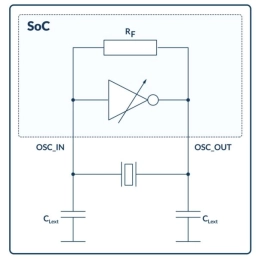
Crystal Oscillators
- The crystal oscillator macros are available in a wide range of industry-standard quartz crystals and MEMS resonators operating in the fundamental mode in the 32 kHz to 80 MHz range.
- These oscillators, which are both power and area efficient, have a programmable transconductance to allow users to find the optimal balance between jitter and power consumption.
-
Free running oscillators
- Compact and low power
- No external components
- Baseline CMOS logic process masks only
- Excellent frequency precision over PVT after trimming