JESD204 Frame Mapping explained from converter samples to lanes

Overview
The JESD204 Transport Layer oversees converter data mapping onto a set of JESD204 Lanes. The nature of these lanes is dependent on the version of the JESD204 standard and a function of the PCS and over the years despite the Serdes technology changing with ever increasing line rates, the function and features of the Transport Layer remained the same. The task at hand is to combine data from multiple converters sampling in parallel across a common set of lanes. With variable converter resolution/sampling width, number of converters and number of lanes this mapping and lane sharing can take multiple forms. This article will explain the basics of JESD204 converter data to frame mapping with all the minute details, demystifying the plethora of single letter abbreviations found in the JESD204 standard.
What is a JESD204 Frame?
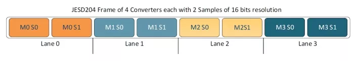
First let’s define what a JESD204 Frame is, with that in hand we can look at how to distribute it across JESD204 Lanes. There are two aspects to a JESD204 Frame, the first being all the data the frame will carry, and the second the space allocated across our JESD204 Lanes. Let’s begin with the data and also review the required padding. With JESD204 carrying converter samples, in most cases sampling the same phenomenon, it is a good starting point to group a single sample from every convert into a data set. The number of mapped converters into a Frame is denoted by (M). To calculate the data size, we must also know the resolution of the converter (N) or in other words the number of bits in a sample. It is worth mentioning here that in some combinations of M and N the data size does not nicely map into the space allocated for the Frame and it is more effective to map multiple converter samples into a single frame, or cases where oversampling is needed, this is possible by specifying (S) the number of samples for each converter mapped into a single frame. Placing Converter samples into a single long vector we obtain our JESD204 Frame Data.
Allocating Frame Space Across JESD204 Lanes
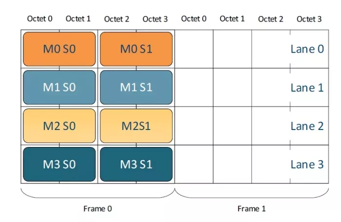
Next lets focus of allocating space for the frame data across the available JESD204 Lanes. The number of Lanes available for mapping is denoted as (L) and the diagram above suggests a quite straight forward split into 4 lanes that would result in a frame looking like the one depicted below. Here one more assumption is made that of the Frame size or length. It is always measured in Octets (8 bits) and denoted by the letter (F) that calls out the number of octets in a frame on each lane. Each active Lane will be allocated F*8 consecutive bits towards the frame container and the converter samples will be placed into this container consecutively.
Key Sizing Indicators
We learned about the most critical sizing indicators in JESD204 some of them dictated by Physical constraints M- number of converters, L- number of Lanes, N- Converter resolution, but also logical mapping ones like F- number of octets per frame determining the frame size and S- number of samples of each converter mapped into a single frame. With these key elements we can now focus on data mapping rules and additional features that further determine the precise data placement that might impact the system design.
High-Density (HD) Mode: Split or No-Split
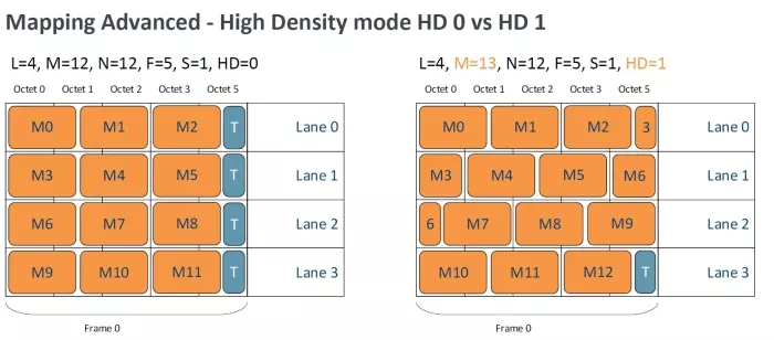
Firstly we will discuss (HD) the High-Density mode that determines if samples can be split on the lane boundaries. If HD mode is disabled, the samples cannot split on lane boundaries and instead tail bits must be added to pad out the remainder of the frame container on the lane. This might be helpful if lanes are split between multiple devices with one logic device communicating with multiple converters. It can however lead to some inefficiencies especially when Samples don’t map into full octets on each lane. When HD mode is enabled, the samples can be split and a part of a sample can be sent on one lane and the remainder on the next as depicted below, allowing for a more tightly packed frame.
Per-Sample Control Bits (CS) and Nibble Extension
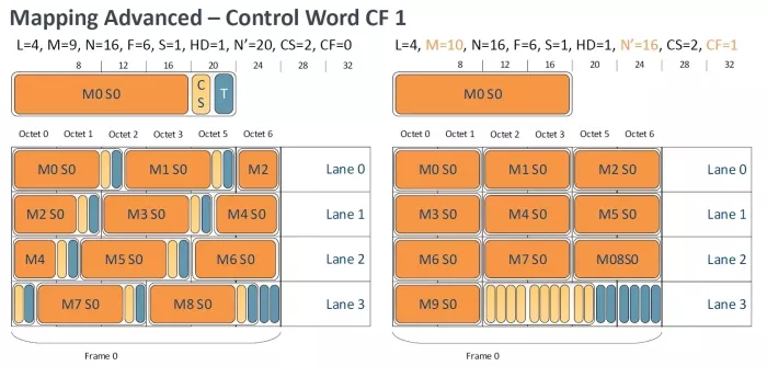
The next advanced topic in frame mapping are per sample control bits (CS) which accompany each converter sample and can be 0-3 in quantity, these are user defined bits and passed through the JESD204 channel together with the samples. They are often used for indicating Under range/Over range, trigger information, or sample validity. These are often placed together with the samples into Nibble Extended Sample containers of length (N’). These containers have to be a multiple of 4 bits (nibble) in length and often carry the N-Sample bits + CS-Control bits + T tail bits. With converter resolutions of 14 or 15 bits this is quite nice as the standard suggests nibble extending all samples so mapping those into 16-bit containers there is some resulting padding space where the control bits can fit with ease. But in a case where the converter sample is 12 or 16 bits this is less optimal, and placing the control bits together in a single group of data at the end of the frame in a Control Word can be more optimal and is indicated by the (CF) parameter.
Conclusion
As final notes we would like to mention the standard allows for having a larger frame than the frame contents, with added padding if needed, and empty unmapped lanes still active on the link. It is a common practice if the frame does not map nicely to double the value of F and obtain a larger framing space and to map double the number samples for each converter which often resolves mapping issues.
In conclusion JESD204 data mapping can be complex and intimidating but it does follow this specific set of rules and allows for quite a lot of flexibility. Our hope is that this article will help you understand the options better, and as always please reach out to us if you have any questions or a project that could make use of our JESD204 IP Cores.
Explore JESD204 IP:
Related Semiconductor IP
- JESD204D Controller IP
- JESD204C Controller IP
- JESD204B Controller IP
- JESD204 Verification IP
- JESD204
Related Blogs
- From guesswork to guidance: Mastering processor co-design with Codasip Exploration Framework
- MACsec Explained: From A to Z
- Reducing design cycle time for semiconductor startups: The path from MVP to commercial viability
- From vision to reality in RISC-V: Interview with Karel Masarik
Latest Blogs
- Ensuring reliability in Advanced IC design
- A Closer Look at proteanTecs Health and Performance Management Solutions Portfolio
- Enabling Memory Choice for Modern AI Systems: Tenstorrent and Rambus Deliver Flexible, Power-Efficient Solutions
- Verification Sanity in Chiplets & Edge AI: Avoid the “Second Design” Trap
- Embedded Security explained: Cryptographic Hash Functions