Accurate System Level Power Estimation through Fast Gate-Level Power Characterization
Abstract
Low power consumption is becoming a critical factor for System-on-a-Chip (SoC) designs. System level power estimation for SoCs has gained importance with the increase of SoC design complexity. This paper presents a high-level power estimation methodology for processors in the context of digital SoCs. It is based on SystemC TLM (Transaction Level Modelling) models including a cycle accurate ISS (Instruction Set Simulator) for simulation performance aspects and on fast characterization from gate-level implementations for accuracy aspects. The experiments show that for average power estimation and power curve estimation, an excellent accuracy has been reached and simulation performance is greatly improved compared to the gate-level.
1. Introduction
In addition to speed and area, low power has been the crucial design requirement of SoCs for a long time. Different power optimization techniques are applied [1] at different abstraction levels in the VLSI design flow. Power estimation techniques are used at each abstraction level to calculate power or energy dissipation with certain accuracy and thereby gain confidence in the power consumption of a design and evaluate the effects of power optimization.
At the highest abstraction level (the functional level), the current SoC design methodologies define the overall functions and determine the cost metrics, such as power consumption. The power related design choices made at this level have the most significant impact on power saving. Power estimation techniques used at this level are mostly based on spreadsheet approaches. The drawbacks of those methods are outlined in [2]. This spreadsheet approach is very time consuming and error–prone as to the expected coverage of all the operating scenarios for a very complex SoC, especially where power management techniques are applied.
In addition, it also cannot accurately estimate the impact of software on power consumption.
At the implementation level (RTL) and the circuit level (gate–level), power estimation tools are already available from either EDA commercial vendors (e.g. Synopsys PrimePower or Sequence PowerTheatre) or in–house providers. These tools can estimate power consumption very accurately. For gate–level power estimation, a 10% deviation from real silicon can be reached, for RTL power estimation, a 15–20% deviation. However, simulation at these levels for an entire SoC is quite slow. Power estimation comes also quite late in the design cycle.
At the architectural level (the level between the functional level and the implementation level), a complete SoC is modelled in a high–level language such as C, C++, SystemC or Java. Based on this target architecture the intended application programs are developed. A lot of Electronic System Level (ESL) design methodologies are being developed to decrease the design productivity gap and to shorten time to market. However, there is not much power estimation tooling available. This leads to a lot of research activities with respect to system level power estimation.
The goal of the methodology described in this paper is to create a high–level power estimation flow that is :
- more accurate than a spreadsheet approach
- much faster than RTL/gate–level power estimation
We present a new methodology that provides power estimation at the early design stage, such that a designer can quickly consider different design alternatives.
The remainder of this paper contains the following sections:
- section 2 discusses related work and highlights our contributions
- section 3 presents our power estimation methodology and its flow; system–level modelling, power modelling and power characterization are also described
- section 4 presents the validation experimental results
- section 5 presents our conclusions and provides an overview of future work
In this section, system–level power estimation techniques for SoCs are discussed and our contributions are highlighted. [5] has proposed a hybrid approach for core–based system–level power modelling. High–level models have been used to speed up simulation and low–level core–based characterization has been used to improve estimation accuracy. Our approach has similar ideas as this one. However, we use transactions based on the standard SystemC TLM modelling instead of instructions of each core used in [5]. We also take power consumption of SoC–level clock trees, interconnectivity and I/O pads into account.
In [8], SystemC TLM based power estimation techniques have also been proposed. They have developed a hierarchical organization of the Transaction Level characterization data. The data used in SystemC TLM models depends on the models characteristics in a system. In our approach, we explicitly distinguish eight component types and we take all the transactions for each component type into account. Each component type has different power characteristics that will be incorporated into its SystemC TLM model.
The power modelling we use is state/mode–based, similar to the one described in [2][4] in combination with transactions. We embed a power model in an existing functional TLM model instead of writing its standalone power state machine as a separate power model. In [11], state–based power models of the individual components have been completely inferred from the datasheet information. However, the datasheet information of each component in a SoC is not always available. In this paper, we also present power characterization methods to derive average power values or energy values for power models. Based on gate–level/analog simulations, we create a power table for each type of component.
In [12] and [13], the instruction set is also characterized in order to obtain energy figures for each instruction, but this is done only through measurements of a board, which means very late in the design trajectory. In [12], no results are given for power curves over time. In [13], results shown do not have a very large dynamic.
In [14], results are good for power estimation, characterization is also done from a gate-level description, but the characterization effort, requiring weeks for the processor for example, is far too important. We want to perform characterization of all blocks composing the system in less than a day.
3. Power methodology and flow
In order to accomplish our goal of having both faster than gate–level/RTL power estimation and more accurate than static methods, we propose a power estimation methodology for SoCs at the architectural level. Based on power estimates on this level, designers can optimize the architecture of the SoC, take measures to reduce the energy used by the processor running the SW on the SoC, or reduce power that is consumed by certain hardware parts in the SoC.
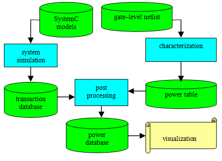
Figure 1: Power estimation flow
3.1 Power estimation flow
The power estimation flow consists of the steps illustrated in Figure 1. We implemented this flow into a toolset called SLEEP. Our power model is generic, but the requirements for accuracy and characterization efforts depend on the type of component being modelled and on how large its power contribution might be in a whole system. Our power model can therefore be seen as heterogenous, even if the model itself is generic.
3.2 FSM Power model and parameters
The power modelling is based on a coarse–grain Finite State Machine (FSM) that will be incorporated into an existing SystemC TLM/PVT functional model. The states of this FSM are related to the power modes of the component which is modelled.
Examples are active mode, sleep mode and idle mode, which will determine the power consumption of a component. Per mode, it is possible to assign leakage power dissipation, average dynamic power dissipation and energy dissipation per transaction. Between modes, a switch energy can also be given.
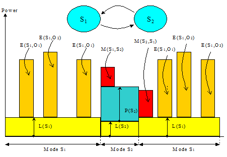
Figure 2: FSM power model example
The power consumption for each FSM power model takes the following parameters (as illustrated in Figure 2) into account:
- the set
 indicates the set of states in the FSM, N being the total number of states; T(Si) represents the total time duration of the state Si over the whole simulation
 - in each state Si, the static power dissipation is indicated by L(Si), corresponding mainly to leakage
- in each state Si, energy per transaction Oj is indicated by E(Si, Oj); the total number of occurrences of Oj is given by n(Si, Oj) over the whole simulation
- the energy to switch from state Si to state Sk is given by M(Si, Sk); the total number of occurrences of such a switch is given by n(Si, Sk) over the whole simulation
- in each state Si, the average power for all transactions can be given by P(Si); it is aimed to be an average of E(Si, Oj) over state Si, when transaction based energy values are not available; P(Si) is therefore frequency dependent
The total energy Etot of each component can be obtained by summing all the possible contributions over time. It is formulated as the following equation:

From that total energy, we can derive the average power figure for a given time interval. The power curve over time uses the same formula, but in addition, each energy contribution is accurately located in time.
3.3 Parameter characterization
Characterization is made at the gate–level, but its required accuracy depends on its type and importance in a system. There have strong requirements on the amount of time needed to perform the characterization. For a processor, the full characterization should not take more than a few days.
3.3.1 Hardware IP
We need here an average level of power per mode, because the expected contribution of these blocks is quite low in comparison to cores, caches and memory blocks. We distinguish here at first 3 modes:
- low power mode (LOW)
- iddle mode (IDLE)
- active mode (ACTIVE)
The LOW mode corresponds mainly to a leakage value. The IDLE mode adds a dynamic figure for the clock tree on top of leakage.
For the ACTIVE mode, we compute the mean value and the standard deviation of the distribution of average power obtained over a set of representative configurations. The value of the standard deviation is a good indication of the accuracy of our characterization.
Within SLEEP, we have written a tool to perform that process automatically.
3.3.2 Processor
We have here also a LOW mode, an IDLE mode and an ACTIVE mode. In ACTIVE mode, we want here to get a power table with an accurate average energy dissipation for each instruction.
In order to achieve this goal, we adopted the following method:
-
initial estimation of energy E(nop) of a NOP (a NOP being an instruction doing nothing, taking a clock cycle), and also the energy E(bch) of a branch instruction, using simple assembly programs
-
initial estimation of the energy consumption of an instruction in the middle of NOP's
-
instruction grouping, depending on homogeneity criteria
-
computation of a correction factor for each group based on the execution of relevant applications
The initial estimation of the energy of each instruction is using the following method:
- for each other instruction, we create a small program Pinst repeating N times the following process:
→ execute the instruction on those registers
→ perform a high number of NOP's
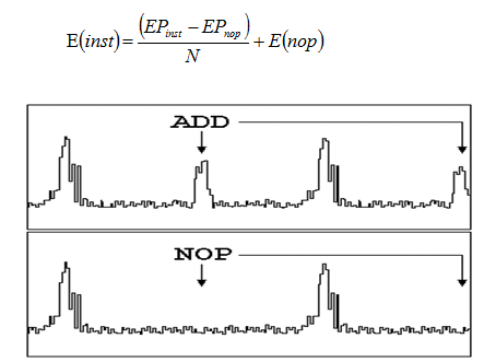
- we generate a program Pnop from Pinst by replacing the execution of an instruction by one or multiple NOP's, resulting in the same period length for the whole process
- we execute the programs Pinst and Pnop on a gate level power estimator able to generate a power curve over time for both Pinst and Pnop (see example on figure 3)
- we calculate the integral of power between the middle of the first serie of NOPs and the middle of the second serie of NOPs, we sum over the N loops to obtain two energies EPinst and EPnop
- we derive the energy E(inst) of each instruction by computing:
Instruction grouping consists in creating G groups depending on criteria of homogeneity. We used so far 2 kinds of criterion:
- homogeneity in energy
- homogeneity in functionality
Finally, we calculate correction factors with the following method:
- we run a relevant application on the ISS in the SystemC environment to extract a trace file and on the gate–level netlist to generate a power curve
- we compute a vector of G multiplication factors applied to energies of the G groups of instructions so that the power curve reconstructed with SLEEP from the trace file has a minimal difference with the power curve extracted from the gate–level simulation
- we apply each multiplication factor of a group on each of its instructions to obtain its final energy figure
For cache accesses, we use the same kind of techniques as the one used for core instructions, by using an initial value taken directly from the memory blocks composing the cache, and by applying some correction factors for:
- instruction cache access energy
- data cache access energy
- instruction cache fetch energy
- data cache fetch energy
Memory blocks have a simple model, with 2 modes:
- low power (LOW)
- active mode (ACTIVE)
In LOW mode, we have only some leakage. In ACTIVE mode, we also have some clock dissipation, and an energy figure per memory access. We distinguish here read and write operations. We can get those values directly from the gate level memory models of memory blocks.
3.3.5 Network
We use one mode (ACTIVE). In this mode, we want to compute the average energy dissipation of a bit toggle on address or data bits. In order to do that, we run some application examples that exhibit communications on the network, and we measure:
- energy dissipation of a whole network: Etot
- energy dissipation of the clock: Eclk
- number n of bit toggles on address and data bits
The value Emean we look for is equal to:

3.3.6 Other components
For the I/O, we directly use the gate–level memory model of the I/O pad.
For the clock tree, we need the average power dissipation P as a function of frequency. We compute it through the estimation of the total capacitance C and the formula:

3.4 SystemC instrumentation
We need to instrument the SystemC description according to our findings during characterization. We achieve that by means of a C++ class called power monitor. The API of this C++ class is the following :
- indicateMode : mode change
- indicateTran : operation executed
- indicateVect : network vector change
- indicateFreq : change of frequency
- indicateVolt : change of voltage
For blocks described with P parameters, we simply make use of indicateMode. For blocks described by E parameters, we make use of indicateTran (memories) and indicateVect (networ). For the power management unit, we use indicateMode for the block itself and we also use indicateFreq and indicateVolt for each frequency domain and for each voltage domain.
For processor core and cache accesses, this is automatically done through the generation of a trace file by the instruction set simulator. This requires, for each type of processor, a post–processing tool to translate the trace file into the event database.
4. Experimental results
In order to provide guarantees to system integrators, we validated separately each part of the system. We present here our results for each kind of block.
4.1 Validation for memory
For memories, the power model at the system–level is identical to the power model at the gate–level, in the sense that each read or write access is recorded. We just checked here that we have indeed the same accuracy by using our tools. Results are within 10 % ot gate-level estimation.
4.2 Validation for network
We took as examples 2 kinds of network:
- AXI network (Advanced eXtensible Interface)
- AHB network (Advanced High–performance Bus)
For each network, we made our characterization and we ran different applications on the netlist, exhibiting some network communications. The values estimated by our approach and the values obtained through a gate–level estimation are within 10 %. Furthermore, power curves over time are very close to each other.
4.3 Validation for hardware IP
We just need to check that the order of magnitude of power estimation is correct, since those components will not represent an important power contribution. We used here as examples:
- a memory controller for AXI
- an interrupt controller for AHB
We could observe that the power estimation with our method gives a maximum deviation of 30 %.
4.4 Validation for core and caches
For core and caches, we need here much more accuracy. We conducted here experiments on 2 subsystems:
- experiment 1 is based on an ARM11 (see [16]) and an AXI bus
- experiment 2 is based on a TriMedia TM3271 (see [17]) and an AHB bus
Each subsystem is modelled in SystemC TLM for performance analysis.
The computation of the initial characterization for each experiment took 10 hours, following our method. In those experiments, the industry standard Dhrystone 2.2 is used to obtain the corrected power table for the processor.
For each experiment, we ran applications on:
- the SystemC virtual platform (where a cycle accurate model is used)
- its corresponding implementation (where a gate–level netlist of the processor is used)
In experiment 1, we used MP3 and MP4 decoding applications, results are shown on figure 4. We obtained here a speedup of 1300.
In experiment 2, we used MPEG2DVS and JPEG decoding applications, results are shown in figure 5. We obtained here a speedup of 100.
Power estimation results for both experiments are summarized in table 2.
We used the same frequency for gate-level and for SLEEP. We observe and excellent correlation (within 5 %) between the SystemC power estimation and the gate–level power estimation, for both average power and power curve over time.
| exp | software | gate–level (mW) | SLEEP (mW) | Δ (%) |
| 1 | MP3 | 3.16 | 3.23 | +2.1 |
| MP4 | 2.62 | 2.51 | –4.2 | |
| 2 | MP2DVS | 256.0 | 251.0 | –1.9 |
| JPEG | 72.3 | 70.1 | –3.0 |
Table 2: Power estimation results
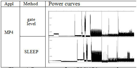
Figure 4: Power curves for ARM1176 core and caches
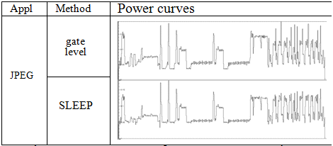
Figure 5: Power curves for TM3271 core and caches
5. Conclusions and future work
We have developed a system–level methodology and flow for digital SoC power estimation. We have addressed how power models can be built into the existing SystemC TLM models based on our existing SystemC TLM design methodologies. Using SystemC design methodologies, simulation performance can be significantly increased. We have also shown that we can use existing low–level implementation of components to quickly characterize power values in order to increase accuracy of power estimation.
The validation experiments show that for both average power estimation and power curve estimation, an excellent accuracy compared to the gate level power estimation has been reached.
In addition, since we already include voltage and frequency dependencies in our flow, we can now study the impact of voltage and frequency scaling at the SystemC level. We also look into the study of options of memory mapping on power consumption. Therefore, our environment, for both characterization and SystemC flow, reveals to open lots of opportunities for performing design space exploration for power with confidence.
References
[1] D. Soudris, Ch. Piguet and C. Goutis, “Designing CMOS Circuits for Low Powerâ€, Kluwer Academic Publisher, 2002
[2] R.A. Bergamaschi, Y.W. Jiang, “State–Based Power Analysis for Systems–on–Chipâ€, DAC2003, June 2–6, 2003, Anaheim, California, USA, pp 638–641
[3] Th. Grötker, S. Liao, G. Martin, S. Swan, “System Design with SystemCâ€, Kluwer Academic Publishers, 2002
[4] L. Benini, R. Hodgson and P. Siegel, “System–level Power Estimation And Optimizationâ€, ISLPED 98, August 10–12, 1998, Monterey, CA, USA, pp. 173–178
[5] T.D. Givargis, F. Vahid, J. Henkel, “A hybrid approach for core–based system–level power modelling, Proceedings of the Asia South Pacific Design Automation Conference, January 2000, pp. 141–145
[6] T.D. Givargis, F. Vahid, J. Henkel, “Trace–driven System–level Power Evaluation of System–on–a–chip Peripheral Coresâ€, Proceedings of the 2001 conference on Asia South Pacific design automation, pp. 306–311, 2001
[7] C. Talarico, J.W. Rozenblit, V. Malhotra, A. Stritter, “A new framework for power estimation of embedded systemsâ€, Computer Volume 38, Issue 2, Feb. 2005 Page(s): 71–78
[8] N. Dhanwada, I.C. Lin, V. Narayanan, “A Power Estimation Methodology for SystemC Transaction Level Modelsâ€, CODES+ISSS’05, Sept. 19–21, 2005, Jersey City, USA
[9] J.F. Edmondson et al, “Internal Organization of the Alpha 21164, a 300 MHz 64bit Quad-issue CMOS RISC Microprocessorâ€, Digital Technical Jounal, Vol. 7, No 1, 1995, pp.119–135
[10] N. Jouppi et. al, “A 300 MHz 115w 32 bit Bipolar ECL microprocessorâ€, in IEEE Journal of Solid State Circuits, Nov. 1993, pp. 1152–1165
[11] T. Å imunić, L. Benini and G. De Micheli, “Cycle–Accurate Simulation of Energy Consumption in Embedded Systemsâ€, pp.867–872, DAC 99, New Orleans, Louisiana
[12] V. Tiwari, S. Malik and A. Wolfe, “Instruction Level Power Analysis and Optimization of Softwareâ€, Journal of VLSI Signal Processing, No 13, pp. 223–233, 1996
[13] H. Shafi et al, “Design and validation of a performance and power simulator for PowerPC systemsâ€, IBM Journal Research and Development, Vol 47, No 5/6, September–November 2003
[14] S. Abrar, “Cycle–Accurate Model and Source–Independent Characterization Methodology for Embedded Processorsâ€, 17th International Conference on VLSI Design, 2004
[15] D. Elleouet, N. Julien, D. Houzet, “A high level SoC power estimation based on IP modelingâ€, 20th IPDPS, 2006
[16] ARM1176 processor documentation, http://www.arm.com
[17] TM3271 processor documentation, http://www.nxp.com
Related Semiconductor IP
- NPU IP Core for Mobile
- MSP7-32 MACsec IP core for FPGA or ASIC
- NPU IP Core for Edge
- Specialized Video Processing NPU IP
- HYPERBUS™ Memory Controller
Related White Papers
- Towards Activity Based System Level Power Estimation
- A Chip IP Integrator for System Level Design
- EDA focus shifts to system level design
- The Challenges and Benefits of Analog/Mixed-Signal and RF System Verification above the Transistor Level
Latest White Papers
- Ramping Up Open-Source RISC-V Cores: Assessing the Energy Efficiency of Superscalar, Out-of-Order Execution
- Transition Fixes in 3nm Multi-Voltage SoC Design
- CXL Topology-Aware and Expander-Driven Prefetching: Unlocking SSD Performance
- Breaking the Memory Bandwidth Boundary. GDDR7 IP Design Challenges & Solutions
- Automating NoC Design to Tackle Rising SoC Complexity