Staged Scenario Generation For SoC Verification
Pune India
Abstract:
SoC (System-on-Chip) involves number of IP blocks and verification of these blocks and interaction within these blocks is a complex procedure. Various methodologies such as eRM (Cadence/Specman) [1], RVM (Synopsys/Vera) [2], VMM (System Verilog) [3] are used by verification engineers to make SoC verification controllable and reusable. These verification methodologies definitely help to reduce efforts of SoC verification. However, problem faced these days is reuse of device level test infrastructure at system level and to generate complex test scenarios. Also challenge for verification engineers is to manage reusability, controllability and scalability of stimulus from device level to system level. Complexity of generating test scenario increases as verification progresses from device level to system level. This paper presents a staged scenario generation methodology for SoC verification to control, reuse and scale transaction generation from device level verification to system level verification. This methodology can provide various levels of transaction generation abstraction to reuse, control and scale stimulus to generate test scenarios for device level as well as system level.
1. Introduction
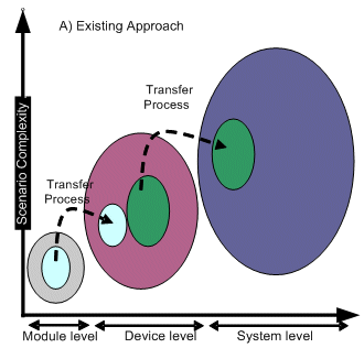
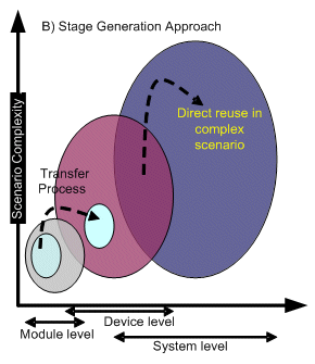
Verification consumes up to 50-70% of the development effort in today's multi-million gate ASICs, Intellectual Property (IPs), and SoC designs. A variety of approaches are used to ensure that all bugs are caught in verification before the design goes to silicon. Present reusable verification methodologies provide guidelines to reuse module level components like monitor, reference models, transactors and assertions at system level verification. Interestingly not much attention is paid to reuse test cases or test case development infrastructure like GENERATORS. It is a great challenge to generate complex test scenarios at system level. Generation of system level test scenario by reusing device level generators can be achieved by using our proposed staged scenario generation methodology. SoC has number of devices communicating with each other using on-chip bus. Verification for SoC normally follows bottom-up verification approach i.e. module level à device level à sub system level à system level. A typical verification environment using HVL (Higher Level Verification Language) has generators, transactors, checkers & monitors for stimulus generation and transaction validation. Abstraction (Nature) of stimulus changes as we progress from module level to system level. At module level, abstraction of stimulus is very close to bus and ports of module; where as at system level abstraction of stimulus would be close to actual application of SoC. In this paper we have explained how stimulus generated at lower level can be reused to generate stimulus of higher level.
2. Existing Stimulus Generation Methods
- Direct signal/pin driving
- Direct BFM (Bus Functional Module) control
- Transaction level control
- Scenario level control
- Number of constraints to be coded and its complexity increases as we move from lower level to higher level test case abstraction.
- Reusability of constraints is difficult as we progress from lower level to higher level.
- Tool requires more time/resources to resolve constraint, as constraint complexity and their number increase.
3.1 Methodology
In this methodology stimulus generation process is proposed in following different stages
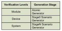
Figure 1: Verification levels
- Atomic generator
- Stage0_scenario generator
- Stage1_scenario generator
- StageN_scenario generator
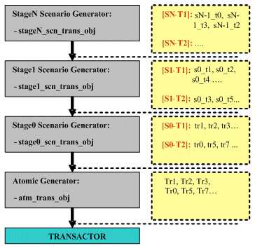
3.2 Stage Scenario Generator
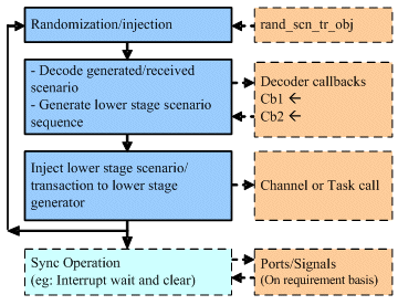
Each stage in this methodology has a stage scenario generator. Following steps are executed by the stage scenario generator as show in figure-3
- Randomization/Injection
- Decoder
- Inject to lower stage
- Synchronization operation (Optional)
3.3 Advantages of Staged Scenario Generation Methodology
- Controllability
- Scalability
- Stimulus generation can be scaled from device level to system level without modifying lower level generator to implement more complex scenarios.
- Stimulus can be generated for one transactor/BFM or for multi transactors/BFMs in stage scenario generator.
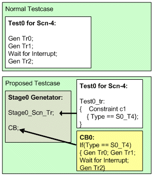
- Each stage in staged scenario generation can add new scenario decode callback as and when needed without any modification to generator.
- Reusability
4. Compatibility with Existing Methodology
Proposed staged scenario generation methodology is an extension to existing generation methodologies in VMM/RVM.
- The first generator in this chain is normal atomic transaction generator same as defined in VMM/RVM methodology.
- Each stage generator is an atomic generator with randomized object of its own transaction class. The only addition is that after stage scenario is generated it will be decoded by callback mechanism. Callback mechanism will create sequence of lower stage scenarios which will be injected to lower stage generator.
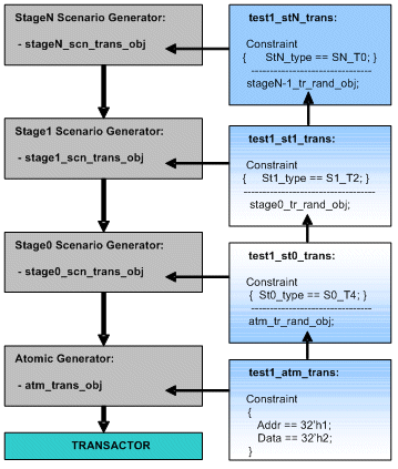
- Each stage randomized object can be replaced by test case with its derived class instance with additional constraints.
- Injection to lower stage can be same as sending transaction to transactor from atomic generator. Higher stage generator will inject in a channel and lower stage can receive it from the channel between these two stage generators.
Practically we have used this approach for verification of NAND Flash Controller. Stage-0 is used to generate sequence of AHB transaction required to configure NAND Flash Controller to initiate command to NAND Flash memory for data storage or retrieval. Stage-1 was used to generate scenario like to perform status read![]() page write
page write![]() page read
page read![]() block erase
block erase![]() status read
status read![]() page read. At system level we have used stage-2 generator which controls stage-0 generator to generate NAND commands to perform data transfer from NAND Flash Memory to DDR and vise versa as required by the system level scenario. Callbacks are appended in stage-0 generator which decodes command type of stage-0 scenario transaction class and returns list of AHB transaction which configures NAND Flash Controller to initiate command to NAND Flash Memory. Device level test case only has constraint to select command type. Stage-2 generator generates stage-0 scenario transaction by constraints on command type as required by system/stage-2 scenario. This way all logic required for each scenario generation is embedded in generator and not in test case, thus logic used at lower level of generation became reusable from device to system level.
page read. At system level we have used stage-2 generator which controls stage-0 generator to generate NAND commands to perform data transfer from NAND Flash Memory to DDR and vise versa as required by the system level scenario. Callbacks are appended in stage-0 generator which decodes command type of stage-0 scenario transaction class and returns list of AHB transaction which configures NAND Flash Controller to initiate command to NAND Flash Memory. Device level test case only has constraint to select command type. Stage-2 generator generates stage-0 scenario transaction by constraints on command type as required by system/stage-2 scenario. This way all logic required for each scenario generation is embedded in generator and not in test case, thus logic used at lower level of generation became reusable from device to system level.
6. Conclusion
This staged scenario generation methodology provides guidelines to implement controllable, reusable and scalable stimulus generator by dividing generation process in different stages. The lowest stage of generation uses atomic generator provided by HVL. Higher stage of generation is accomplished using generator class which creates constraint scenarios and injects them to lower level generators. Constraint management and scenario controllability is achieved through callback mechanism. Test case development becomes simpler and reduces to implementing callbacks and calling them as per the need. Thus, complex scenarios can easily be created by cascading different staged generators where lowest level is nearer to the design ports and protocols and the highest level is nearer to the application. Cascading of stages can be achieved using HVL mechanisms like channels. Practically we have used this methodology for NAND Flash Controller verification with 2 stage generation and reused at system level verification adding third stage.
7. References
[1] eRM reference manual Version 2.1.
[2] RVM User Guide Version 8.6.1.
[3] VMM for System Verilog by Janick Bergeron, Eduard Cerny, Alan Hunter and Andrew Nightingale.
[4] System Verilog LRM 3.1a.
Related Semiconductor IP
- NPU IP Core for Mobile
- NPU IP Core for Edge
- Specialized Video Processing NPU IP
- HYPERBUS™ Memory Controller
- AV1 Video Encoder IP
Related White Papers
- Simplifying SoC Verification by communicating between HVL Env and processor
- Creating core independent stimulus in a multi-core SoC verification environment
- Fast, Thorough Verification of Multiprocessor SoC Cache Coherency
- Techniques for CDC Verification of an SoC
Latest White Papers
- Ramping Up Open-Source RISC-V Cores: Assessing the Energy Efficiency of Superscalar, Out-of-Order Execution
- Transition Fixes in 3nm Multi-Voltage SoC Design
- CXL Topology-Aware and Expander-Driven Prefetching: Unlocking SSD Performance
- Breaking the Memory Bandwidth Boundary. GDDR7 IP Design Challenges & Solutions
- Automating NoC Design to Tackle Rising SoC Complexity