A UML Representation of a Passive Standby Power Management Architecture for Set-Top Boxes
R. Deaves, A. Lloyd, S. Kulasekara, V. Lakshman, N. Vermaat, E. Vermaat-Cuoco, P. Steiglitz, M. Habets, S. Ryan and A. Jones
STMicroelectronics
Abstract:
The paper provides two main technical contributions: (i) an architecture supporting passive standby for a range of set-top boxes (STBs), and (ii) a UML representation of the specification to provide a clear and concise architecture.
Power management is a vital criterion for the development of STBs providing reduced cost, achieving legislative/governing body consumption figures and retailing ‘green’ products. Passive standby is important as it removes power from the STBs SoCs to achieve the lowest power consumption state.
Our recent work has demonstrated that UML provides benefits in the specification of STB architectures. In this paper UML is applied to the specification of a STB sub-system, i.e. passive standby. An unambiguous specification is essential for power management architecture as it affects all aspects of the SoC requiring developments by multiple teams, working on different sites and in different time zones.
The paper concludes that the architecture specification has been successful and is currently being demonstrated to provide mains power of less than 0.5W for a leading edge STB product. Further, positive feedback was provided from the engineers involved in the project stating that UML provided a clear and concise representation of the architecture. This, coupled to implementation success vindicates the use of UML for the definition of STB sub-system architectures.
1. Introduction
Achieving low power consumption is a critical metric for set-top box (STB) manufacturers in selecting their SoCs. This is motivated by legislation demanding strict power consumption limits [1][2] and an ever increasing number of consumers who choose ‘green’ products.
An important power management mode in the quest for achieving a low power profile is controller passive standby (CPS). Here a Low Power Controller (LPC) exists on its own power island outside that of the SoC. When the SoC detects that no STB functionality is required, e.g. during late night and early morning the SoC enters a state where its power can be removed. In leading edge SoCs that run sophisticated OSs (such as Linux) this preparation may include hibernating onto DRAM memory. The SoC then communicates with the LPC to request removal of SoC power. A low power state is then achieved with only the pertinent DRAM and LPC being powered. The STB has then entered CPS. In this state the LPC will monitor a set of power change triggers. Commonly, these will include front panel switches and infra-red remote controls. When the LPC detects a valid change trigger power is restored to the SoC which enters ‘mission’ mode able to provide STB functionality. The main metrics in accessing CPS is the power consumption achieved and the time to return to ‘mission’ mode.
This paper describes an advanced CPS architecture suitable for a range of state-of-the-art STBs. Realization of the architecture requires developments in a number of areas, under the responsibility of a number of teams located at sites spread across the world. In order to concisely convey the architecture a UML representation of the specification was used.
The remainder of the document is organized as follows: Section 2 documents the CPS options. Section 3 provides details of our recent work on UML and how this is developed in this paper. Section 4 provides a UML representation of an advanced CPS architecture. Section 5 discusses an early implementation of the architecture along with an analysis of the benefit of UML. Concluding remarks and future work details are provided in Section 6.
2. CPS Architecture
The CPS architecture to be specified has the requirement to support a number of options:
- External/Internal Controller: In the latest SoCs the power controller is included on the die of the device.
- Flashless/Flash Resume: This is concerned with the issue of whether the flash is accessed or not when exiting CPS. This is required as the latest flash devices (MLC-NAND) have the characteristic that reading the memory deteriorates its contents.
- Secure/Non-secure Operation: Initial development of STBs is generally carried-out on non-secure platforms. Advanced development and STB deployment are carried out on secure platforms.
Not all combinations of options are supported. Fig. 1 provides a tree diagram representation of valid combinations.
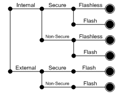
Fig 1: Valid CPS Architecture Options
Architecture representations for all the options have been modeled in UML. The CPS architecture represented in this paper describes one of these options: Internal / Non-secure / Flash. This example highlights the salient points of passive standby while brief enough to be presented in this paper.
3. UML Background and Status
Our recent work has focused on providing support for the hypothesis that using UML in the specification [3][4] of STB architectures provides a useful benefit. In this paper we extend this work by investigating the benefit of using UML for the specification of a sub-system of a STB, that is, CPS. The relationship between our previous, current and future work is represented in Fig 2.
Future work will examine the benefits of applying metrics to the UML of a system to determine architecture complexity. This is analogous to metrics applied to determine software complexity.
This may be useful for project and program management in assessing the effort (in engineering resources) required to realize the architecture.
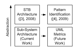
Fig 2: Previous and Current Work
4. CPS Architecture
This section of the paper provides a system level architecture for CPS. Here the architecture is described with UML.
4.1 UML Representation
The UML models used to describe CPS include:
- Use case models to describe the requirements,
- Component models to provide a global view/status of the architecture,
- Sequence diagrams to highlight the order of events to change state, and
- State models to summarize the operation of processing nodes.
4.2 Use Cases
The use cases associated with CPS are represented in Fig 3.
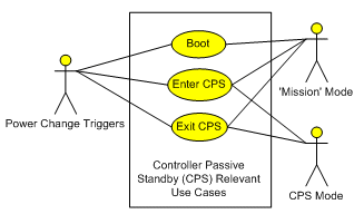
Fig 3: CPS Use Cases
The Actors on the system include Power Change Triggers, ‘Mission’ Mode and CPS Mode. Here the Power Change Triggers include the User pushing a button on the IR handset or front panel. This trigger Actor results in the box entering ‘Mission’ Mode for functionality such as viewing/recording TV; or entering CPS where the box is in a low power mode. Three use cases are considered: (i) Boot, which takes the box from a Power on Reset to ‘Mission’ Mode, (ii) Enter CPS, which takes the box from ‘Mission’ Mode to CPS Mode, and (iii) Exit CPS which takes the box from CPS Mode to ‘Mission’ Mode.
4.3 Boot Use Case
The Deployment Model that represents the CPS architecture is represented in Fig 4. This comprises three parts, the SoC, Flash memory and DRAM memory. The SoC itself comprises IPs (including LPC) and Host. Note here that as the LPC is ‘internal’ it exists on the SoC. These IP include DMAs and transport stream management modules. These IPs execute code from their local RAM. In addition, other forms of IP execute code from external DRAM, e.g. CPUs. The deployment model of Fig 4 provides the status before power on reset (POR).
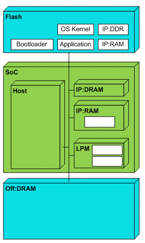
Fig 4: ‘Start’ Deployment Model
The Boot Sequence is provided in Fig 5. On applying power to the STB the Host begins executing the bootloader resident in Flash. The sequence begins by placing the DRAM in the On state. The Host then queries the LPC in order to determine if the re-start is due to a power-on-reset (a Boot) or exiting from CPS. In this use case the re-start is due to a Boot. The bootloader is then conditioned for the boot process.
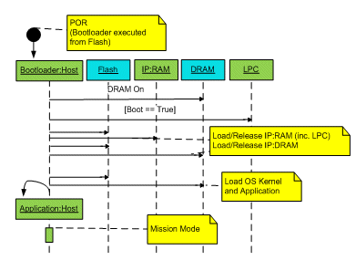
Fig 5: Boot Sequence
The Host continues executing the bootloader by loading and releasing the IPs that execute code in local RAM. This includes loading code to the LPC. The next step in the sequence is to load and release the IPs that execute code from the external DRAM.
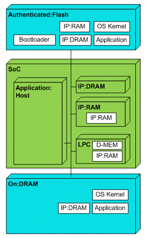
Fig 6: ‘Mission’ Mode Deployment Model
Finally, the bootloader loads the OS kernel and application. The bootloader has then completed its sequence and the OS and application begin execution. The STB is then in ‘Mission’ mode and ready to perform functional use cases, e.g. viewing, recording, playing back video streams. Fig 6 provides deployment model representing the state after the boot use case has completed.
4.4 Enter CPS Use Case
On receiving a power change trigger a sequence of events are carried out to enter CPS. This sequence is represented in Fig 7.
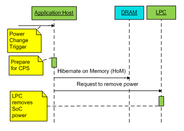
Fig 7: Enter CPS Sequence Diagram
This sequence starts with the application preparing to enter CPS. This includes placing device drivers in states where the power can be removed. Then, the OS performs the operation of hibernating on memory (HoM). This places the OS (and Application) in a state where the power can be removed, and importantly re-applied. The HoM activity also performs the vital stage of storing all pertinent SoC registers that are required to resume execution on exiting CPS. Finally, the HoM operation places the DRAM in a Self Refresh state. This is a low power state for the DRAM which maintains the memory contents.
The final step of entering CPS sequence is for the Host to make a request to the LPC for it to remove the SoC power.
The LPC, on receiving the request removes power from the SoC while maintaining power to the DRAM and LPC. A number of power change triggers will then be monitored by the LPC. On receiving a valid trigger, e.g. front panel switch or IR handset communication, the Exit CPS Use Case will be invoked. This is discussed next.
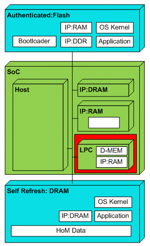
Fig 8: Enter CPS Deployment Model
4.5 Exit CPS Use Case
Re-applying power to the SoC causes a sequence of events represented in Fig 9.
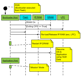
Fig 9: Exit CPS Sequence Diagram
The POR causes the SoC Host to start executing the bootloader. The bootloader then changes the state of the DRAM from Self Refresh to On. The sequence continues with the Host enquiring as whether the re-start is due to a boot or exit from CPS. In this case, the cause is an exit from CPS. The bootloader is then appropriately conditioned. This leads to the reload and release of the IP based on code resident in internal RAM and the re-start of the IPs that use code in DRAM. It should be noted that these images should be able to deal with re-initialising the .data sections. To complete the bootloader sequence the OS performs a resume from HoM. This restores the pertinent SoC registers and allows the OS and Application to re-start.
On exiting CPS the SoC is once again in ‘Mission’ Mode with the state represented in deployment model of Fig 6.
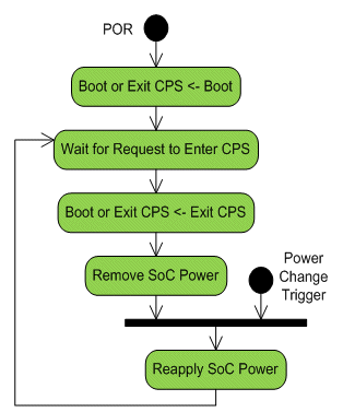
Fig 11: LPC State Model
4.6 Processing Component Views
The deployment models and sequence diagrams of the previous section allows the behavior of the LPC and Host to be clearly defined. These are represented in the state models of Fig 11 and 12 respectively.
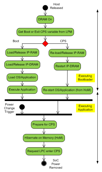
Fig 12: Host State Model
5. Discussion
The architecture presented is currently being developed and applied to a number of STBs. A recent demonstration [5] based on an external controller, non-secure scheme with Flash resume capability showed that low power of <0.5W (at the mains) could be achieved with a resume time of approximately 3 seconds. This used a STi7108 [6] as the SoC and an ST8 based CPU as the external controller. This is represented in Fig 13.
The CPS architecture was presented using deployment models to provide the state of the system at several particular instances. Sequence diagrams were used to highlight the order of events between one deployment model and another. This provided UML ‘animation’ of the architecture. The feedback from the engineers involved was that the use of UML in this way improved the clarity and conciseness of the architecture over non-UML based representations.
Analysis of the UML representation highlights that 9 models were used: 1x use case, 3x deployment models, 3x sequence diagrams, and 2x state charts. Further, the sequences required 13 interactions between 6 deployment nodes resulting in 17 state changes. The full implementation requires changes in three areas, Host: bootloader, application and LPC: firmware running on 2 processing nodes.
The models were presented to 9 teams (security, home video division: system/software architects, tv division: system/software architects, linux team: bootloader/HoM), field application team and program management).
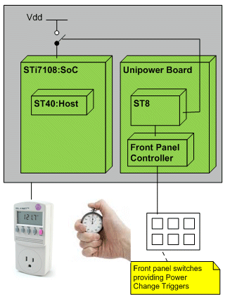
Fig 13: Demonstration Configuration
6. Concluding Remarks
Power management is an increasingly important criterion in the architecture, design and manufacture of STB products. This is motivated by achieving legislative/governing body consumption figures and consumer demand for green products.
Passive standby is a state in which the power is removed from the SoC and an external power controller (LPC) is used to monitor wake-up triggers. This provides the lowest power consumption state for the system (omitting the trivial case of all power removed!).
This paper has presented a sub-system level architecture for implementing CPS in a range of STB platforms. These include today’s technology where an external controller may be employed but also supports the next generation of STBs where the controller will be internal (i.e. on the die of the SoC) and will facilitate MLC-NAND requiring flashless resume.
The technology presented here has been demonstrated at a prestigious consumer electronics trade show/conference showing mains power consumption of less than 0.5W with a resume time of approximately 3 seconds. Our future work will focus on extending the CPS capability already demonstrated to include advanced features such as security and flashless resume.
The use of UML to represent the sub-system architecture generated positive feedback from the teams involved. The comments were that the architecture was clear and concise. The use of ‘animation’ to present the architecture proved popular, as did providing individual processing views to summarize the individual requirements of the LPC and Host.
Currently, analysis of the UML models can provide the program management with a quantitative analysis of the workload required to implement a given architecture. This is based intuitively on high level details of the architecture, e.g. how many teams are involved. Future work may enhance this information with qualitative information pertaining to the architecture. These may be analogous to those used in measuring the complexity of code such as coupling and cyclomatic complexity.
Acknowledgements
The authors would like to acknowledge valuable comments and support from Andrew Cofler, Robert Smart and Yann Garnier concerning aspects of this work. Acknowledgements also to Bill Fletcher, Pierre Le-Bars and Bernard Couzon for program management support; and Phil Smith, Joe Chester, Darren Lucas, Lowry McConnell and Milan Komarek in putting together the demonstration.
References
[1] EU 1275/2008 for Standby States.
[2] EU 107/2009 for Free-to-Air STBs.
[3] Deaves, R.H. et al., ‘Embedded Software Architecture Specification Developments in Support of SoC Design and Re-use’, IPSOC 08, Dec 2008.
[4] Deaves, R.H. et al., ‘Initial Investigations into UML Based Architectural Reference Patterns in Set-top Boxes’, IPSOC 09, Dec 2009.
[5] IBC, RAI, Amsterdam, 9-14th September 2010.
[6] STi7108 Advanced HD decoder with 3D graphic accelaration Datasheet, http://www.st.com/stonline/books/pdf/docs/16790.pdf
Related Semiconductor IP
- NPU IP Core for Mobile
- NPU IP Core for Edge
- Specialized Video Processing NPU IP
- HYPERBUS™ Memory Controller
- AV1 Video Encoder IP
Related White Papers
- Initial Investigations into UML Based Architectural Reference Patterns for Set-Top Boxes
- Effective Optimization of Power Management Architectures through Four standard "Interfaces for the Distribution of Power"
- A Cost-Optimized Set-Top Box Architecture
- Automated Architecture Checking of UML Based SoC Specifications
Latest White Papers
- Ramping Up Open-Source RISC-V Cores: Assessing the Energy Efficiency of Superscalar, Out-of-Order Execution
- Transition Fixes in 3nm Multi-Voltage SoC Design
- CXL Topology-Aware and Expander-Driven Prefetching: Unlocking SSD Performance
- Breaking the Memory Bandwidth Boundary. GDDR7 IP Design Challenges & Solutions
- Automating NoC Design to Tackle Rising SoC Complexity