Increase battery life of Consumer Products using architecture simulation
Akash K (Application Intern) and Deepak Shankar (Founder)
Mirabilis Design Inc.
For a consumer application, the response time, display resolution and battery life are the top features. The lifecycle of the battery is directly proportional to its capacity, power spikes and usage profile. The battery size cannot be increased indiscriminately because of cost, space and reliability considerations. Semiconductor power loss is dependent on capacitance, wire load, gates, supply voltage, signal transitions and leakage current. System power is centered around the display, touch capacitance, processor and memory. The latency, throughput and thermal design power (TDP) of the processor and the processing systems such as single board computers, electronic control units (ECU) and high performance computing are driving criteria in product design. The first algorithm that comes to mind when reducing power is power gating, technique of shutting down the device or network when there is no task executing. This is easier suggested than deployed because of the impact on safety, timing deadlines and cost of implementation.
For any new system, the number of power states, concurrent thread operations, transition times and switching require a detailed power evaluation prior to finalizing the specification. Moreover, the specification must be trade-off between performance, power, functionality and sometimes reliability. The processing options, interface capacity, applications variations, display systems and other MEMS/mechanical systems on today’s system makes it very difficult to predict the power consumption using analytical methods such as Excel. Power measurement requires a combination of a resource and cycle-accurate model to make predictions that have an extremely high probability off occurrence.
System-level modeling using software packages such VisualSim, from Mirabilis Design, or transaction models in C++ have been used for a long time to explore the performance of electronics and semiconductors. Graphical modeling environments like VisualSim allow interactive evaluation of the system while programming languages offer far greater openness. These models will have the definition of the resources, hardware, schedulers, traffic, use cases and network. The cycle-accurate definition of the hardware platform is not a major consideration early in the design process, thought it can be added as the scope of the evaluation narrows to answer specific questions such as the impact of periodic refresh on the power consumption when 1X or 2X. To this timing model, VisualSim has added power exploration, thus offering a complete system analysis solution.
VisualSim is a model-based system simulation software that accelerates development using component-based modeling methodology and provides a large portfolio of reports. The system can be a processor, System-on-Chip, autonomous driving assistance system, flight avionics or an adventure camera. The modeling components can be a resource, FPGA, discrete component, electrical systems, MEMS, processors, distribution-based traffic generator, hardware peripheral and software task graphs. A resource is sub-system that consumes time or quantity. Examples of resources can be a gimbal motor or a accelerometer.
To incorporate power analysis into the system-level simulation, the system model must contain the power per state for each device. The power number can be a value or a combination of voltage, area, switches, leakage and LDO efficiency. An example of a power state value is shown in Table 1.
![]()
Table 1: Expression for the power in a Device State
The model must incorporate the impact of transitions and dynamically move from one state to another state as the use case and traffic executing on a device changes. The change to a new state can be starting a new execution, moving to deep sleep after a period of inactivity, executing a low priority vs high priority use case and specific conditions such as memory Activate and Refresh. The power expression value must change in tandem with the timing attributes such as clock speed and temperature.
The power analysis starts with a table to describe the expression for the power in a state and state machine to handle the management. The simulator or the VisualSim event-calendar must support time-based power measurement, dynamic state changes over time for each resource and device, and transitions between the states based on the application and user activity. The power manager will contain complex expressions with variables to define the power in each state. The expressions can incorporate leakage, area, voltage levels and difference between application tasks. The variables can include the clock speed, number of switches enabled and abstraction to capture wire lengths- both delay and leakage. Monte Carlo simulation can capture jitters, variations over time, use cases, software profile and traffic distributions.
The active power table is an important participant in the architecture exploration and is responsible for collection, providing input to the battery and handle the charging requirements of the battery. The resulting statistics include the energy consumption of the components, cumulative power of the system, instant load, average load and consumption timeline by state for each component.
System-level power exploration can evaluate the merits and the energy saved by various power reduction and low-power techniques. Here we discuss the techniques and explain their impact using a simulation model in VisualSim. For the purpose of this study, we are using a four core processor, dispatcher in place of a Real-time Operating System, 4 concurrent threads and interrupts that are sequenced to trigger the threads on the processing resources. We have parameterized the model for variable clock speeds at the cores, variable number of cores between one and four and an offset between the thread triggering. In addition, we have incorporated the logic for dynamic change in the voltage and clock speed. The block diagram associated with this description is shown in Figure 1.
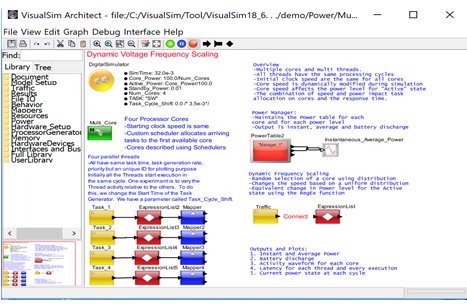
Figure 1: System-level Block diagram of a multi-core architecture and four concurrent threads
The following experiments are conducted and we look at the latency and power consumption for each scenario.
-
Offset concurrent tasks: There are four task and by default these tasks are triggered at the same time. In this experiment, we shift each task by a 3.5 ms. This way the tasks do not all start at the same time. As we see the results from Figure 2, this approach reduces the power spike. The maximum spike goes from 1.0mW to 7.5mW, a 25% savings. From figure 3 the latency has definitely reduced from 7ms to 0.5ms, a significant improvement. The interesting deduction from figure 2 and table 2 is that all the four cores are no longer utilized and there is only an occasional overlap in tasks requests for processing resources. There is no impact on the average power consumption.
-
Comparing a single core running at 1GHz vs 4 cores running at 250MHz: In this experiment, we target all the tasks on a single core which is running at 1GHz speed. We use the offsets for the threads. The results from Figure 2 shows there is a significant reduction in both instantaneous and average power. From figure 3 we can see the latency plot does not have a significant impact. You can see that the peak power is the same as the non-offset value of 1.0mW but the average power is cut in half to 0.15mW. This is because there is considerable wastage of the processing speed.
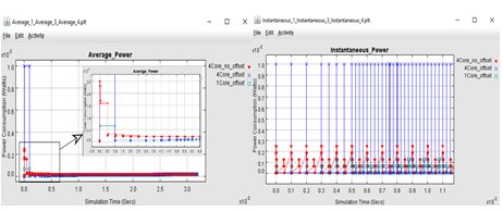
Figure 2: LHS shows the average power over time. The RHS shows instant power over time.
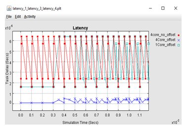
Figure 3: Latency over time.
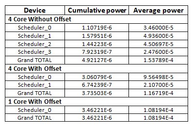
Table 2. Cumulative and Average power for above experiments
The cumulative and average power consumption for one core with offset in tasks is lesser than the 4 core with and without offset.
Dynamic Voltage Frequency Scaling (DVFS): This is the preferred techniques to conserve power and is done by varying the clock speeds based on the requirements of the task. A good example is of an x86 processor that is rated for 3.2GHz but runs at 1.8 GHz on the laptop. Using a prototyping board, it is extremely hard to predict the latency of a task when the voltage is frequently adjusted. In the associated model, we have not implemented a specific algorithm, rather see the change in the power and latency over a wide range of clock speeds. The results are in Figure 4. We are using the four cores and four offset threads for this run. Notice that the power and latency are fluctuating because of variation in clock speed. The latency remained the same as the original offset version. DVFS helps us with large scale power reduction. From Figure 4 we can see that the time slot for all the tasks are not same, as the incoming tasks increases the clock speed varies with each core based on the requirements
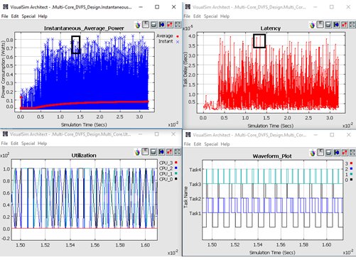
Figure 4: Power, Latency and utilization variation in Dynamic Voltage Frequency Scaling of a four core with four concurrent threads and Uneven Timeslot task in each core
From Figure 4 we can see that the instantaneous power is lesser for higher latency task (Black box in the power plot) vice versa. This illustrate the function of DVFS, where the Clock speed decreases for small processing tasks which in turn increase the latency and decreases the power.
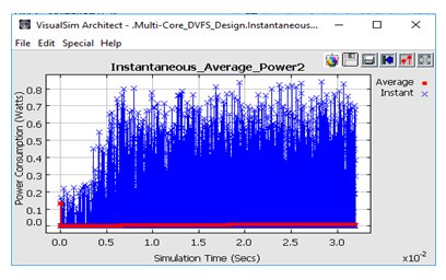
Figure 5: Reducing average power by implementing power management
Forcing the cores to move standby state after a particular period of time will reduce the power consumption. From figure 5 we can see there is a reduction in power after implementing power management.
Extending the DVFS example, it is possible to modify the start and frequency of each task. Analyzing the generated statistics, we can see that the number of cores being utilized reduces (core_3), thus eliminating the extra standby power and reducing the power consumed. As you can see, it is important to explore both the power options and the software dispatch in tandem. This will ensure the required response time while reducing the power consumed.
Power Gating: This is the process of moving the processing unit to a lower power state after a certain period of inactivity. A common example is the laptop going from Active to Standby to Sleep and Hibernate. In this model we add the power gating state machine logic to the Power Table. We set delay to idle state to 10us and the transition time as 1 us. The device stays for a shorter time in the Standby state. From Figure 65 we can see that the cores are changing it states from standby to idle whenever the cores are inactive. The transition time has a minimal to zero impact on the latency.
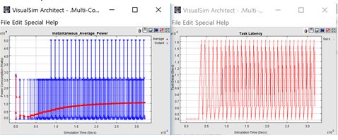
Figure 6: Power Gating where the Cores are moved from Standby to Idle when inactive for 0.1ms with transition time for 1.0us
Conclusion:
System-level simulation can be used for extensive power analysis at both the semiconductor and system-level. Using the power exploration in conjunction with the performance studies ensures that the trade-offs are done in tandem, thus ensuring a higher quality product. A number of power studies can be accomplished at the system-level much before product implementation and eliminates all surprises during integration. A side benefit of this study is that thermal and mechanical engineers get fully validated data, as opposed to approximate best judgment information. Software tools such as VisualSim that have integrated both performance and power analysis into a single system-level model helps construct models faster, reduce model maintenance with smaller set of models and conduct higher quality exploration, early in the design cycle. Also, these system-level tools move the exploration much earlier in the design than was possible previously.
- The implication of offset in each task provides reduction in power consumption and latency.
- Reducing the number of cores and increasing the processor speed gives a significant improvements in power reduction.
- Varying the clock speed of cores based on the requirement of task provides the best way to reduce the power consumption in the system.
- Making the cores idle during inactive periods reduce the wastage of power in the system.
Related Semiconductor IP
- NPU IP Core for Mobile
- MSP7-32 MACsec IP core for FPGA or ASIC
- NPU IP Core for Edge
- Specialized Video Processing NPU IP
- HYPERBUS™ Memory Controller
Related White Papers
- Optimizing multimedia software for consumer products
- Timing key to optimizing audio performance in consumer products
- Power optimization can extend the battery life in your portable multimedia system
- USB OTG: The only wired interface portable consumer products need?
Latest White Papers
- Ramping Up Open-Source RISC-V Cores: Assessing the Energy Efficiency of Superscalar, Out-of-Order Execution
- Transition Fixes in 3nm Multi-Voltage SoC Design
- CXL Topology-Aware and Expander-Driven Prefetching: Unlocking SSD Performance
- Breaking the Memory Bandwidth Boundary. GDDR7 IP Design Challenges & Solutions
- Automating NoC Design to Tackle Rising SoC Complexity