A First time right design methodology for successful development of automotive SoC products
By Haridas Vilakathara, NXP Semiconductors
Abstract
This paper describes the methodology employed during the development of a System on Chip (SoC) platform developed for automotive applications. The methodology is based on the following major aspects.
- Requirement driven development approach based on reusable IP core as the base for SoC integration and development
- Functional coverage based verification approach providing 100% coverage to requirements
- FMEA based risk identification and tracking approach.
In a typical SoC project keeping track of different requirement and the relationship between them is a difficult task. DO-254, Design Assurance Guidance for Airborne Electronic Hardware [1], provides guidance for design assurance across the hardware project life cycle starting from requirement capture to product transition.
Figure[1] show a DO-254 based hardware life cycle adapted to meet a typical SoC hardware design process. The key item of the life cycle is the central planning and control function along with a concurrent process support functions based on the following aspects.
- An effective planning process defining clear milestones within the project execution life cycle.
- Requirement driven development flow, wherein requirement management and traceability across work product is considered as key to project success.
- An FMEA based product risk assessment starting from early concept phase itself, and continues evaluation of the FMEA items and process.
- A concurrent supporting process to ensure process and product assurance along with 100% forward and backward traceability to the requirement process.
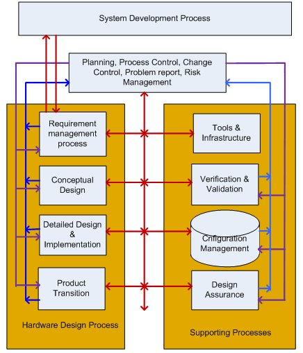
Figure 1 : Development methodology
The following are the major attributes of the hardware life cycle followed.
PLANNING PROCESS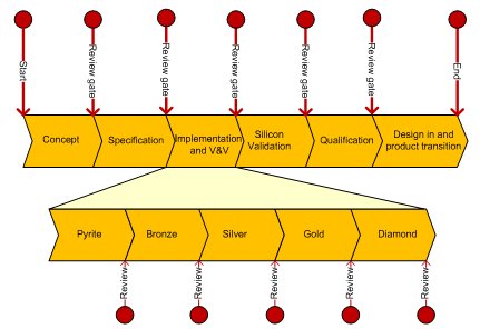
Figure 2 : Project gates
An effective planning process can define a number of gates/milestones, which divide the project up into manageable project phases. Within these project phases activities will be planed to generate a number of deliveries. Each of these deliveries will have their own maturity. It is related to the type of delivery, i.e document, design, hardware, software, etc. based on the maturity model is applied. The longer implementation phase is further sub divided into different phases based on product maturity expectations. At the end of each planned phases, formal reviews and audits are conducted to make sure that the expected process compliance and product level maturity are in place.
| Development phase | Remarks |
| Pyrite | Identify the key IP’s component and their sources. Risk assessment |
| Bronze | Early prototype state. Freeze the top level and component level interfaces. All individual IP’s are Silver quality |
| Silver | Freeze all IP’s. Basic functional verification OK. All IP’s are of gold quality |
| Gold | RTL freeze. Functional coverage 100 % |
| Diamond | Only ECO changes |
FMEA BASED PRODUCT RISK ASSESSMENT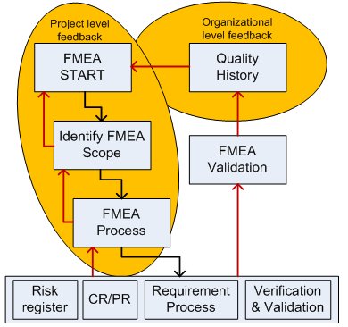
Figure 3 : FMEA process and feedback loop
FMEA is considered as an efficient tool in assessing the product level risk, starting at an early phase of the product development life cycle, and carried throughout the product life cycle and on a continuous evaluation basis. One of the critical aspects of the FMEA flow is the organizational level feedback loop, wherein the inputs are taken from organizational level quality history of similar products, and the FMEA findings are fed back to the quality history repository for future projects. The quality history consists of lessons learned in previous projects, field failure reports, benchmarking reports, and expert opinions etc. The FMEA flow and feedback mechanism is shown in figure[3].The red lines on the left side of the picture indicates the feedback loop at the project level and the red lines at right indicates the organizational level feedback. FMEA validation is a key aspect at the organizational level, where in the effectiveness of FMEA is assessed through product field failure reports.
Within the project the FMEA is conducted at three levels. We will be discussing the first two FMEA items in this paper. The semiconductor manufacturing itself is considered as a matured process, and if not the Semiconductor fabrication house along with process flow validation team will be qualifying the process through various test chip programs. Hence not considered within the scope of the project.
| FMEA Scope | Remarks |
| Concept level | Focuses on potential failure modes associated with the proposed functions or a concept proposal |
| Design level | Focuses on potential failure modes of products caused by design deficiencies |
| Semiconductor Process level | Focuses on potential failure modes of the semiconductor process that are caused by manufacturing or assembly process deficiencies |
Concept phase: The primary strategy is to focus on ensuring right information at the conceptual design stage and then preserving the information integrity as we proceed through detailed design and implementation stage. We found that an early concept level FMEA is a good mechanism to critically evaluate the requirements itself and to validate the concept against the system constraints. Focus is on the interaction between systems at concept level and identifies potential failure modes caused by interactions. This can used to analyze concepts in the early stages before hardware is defined. The following are the benefits of doing an evaluation at an early stage.
- Helps in selecting the optimum concept alternatives, or determine changes to design specifications.
- It also can identify system level testing requirements.
- Helps in determining hardware redundancy and fault tolerance requirements based on failure modes and effects.
- Helps to select the optimum concept alternatives, or determine changes to System Design Specifications (SDS).
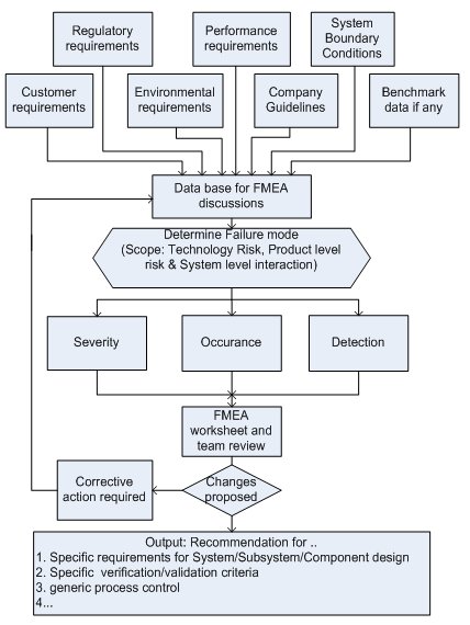
Figure 4 : Concept FMEA
The following are the outputs of the concept level FMEA that may influences the system level decisions
- A list of potential concept level Failure modes and causes.
- A list of actions (and to track) to eliminate the causes of Failure Modes, or reduce their rate of occurrence.
- Decision on redundancy management (if required).
- Specific operating parameters and boundaries as key specifications in the design phase.
- New test methods or recommendations for new generic testing.
- Decision on which concept to pursue.
Design phase: Here again apart from the standard design practices, clear attention is given on doing a design level FMEA based approach in identifying the weak spots in the design. The focus is on identifying potential failure modes of products caused by design deficiencies and the mission profile/boundary conditions of the design. The following are the generic guidelines followed in conducting the design level FMEA.
- Analysis based hardware functions, interfaces or a combination
- HW-SW interfaces can be covered in a separate Software FMEA.
- Consider environmental conditions and its impact on design (EMI/EMC, ESD, Single event upset etc.)
- An identified failure mode may provide additional information to help plan thorough an efficient verification and validation programs.
- It also establishes a priority system for design improvements, provides an open issue format for recommending and tracking risk reducing actions and future reference to aid in analyzing field concerns.
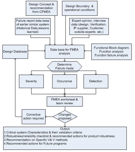
Figure 5 : Design FMEA
The following are the benefits of the design level FMEA that can also influences the design decisions
- Aiding in the objective evaluation of design, including functional requirements and design alternatives.
- Evaluating the initial design against non functional requirements (example environmental conditions such as ESD, EMI/EMC etc.)
- Providing additional information to aid in the planning of thorough and efficient design, development, and validation programs.
- Developing a ranked list of potential Failure Modes according to their effect on the "customer," there by establishing a priority system for design improvements, development and validation and analysis.
- Identify Implementation/verification priorities.
- Providing an open issue format for recommending and tracking risk reducing actions by linking FMEA results CR/PR, Risk register etc.
- Providing future reference, e.g., lessons learned, to aid in analyzing field concerns, evaluating design changes and developing advanced designs.
- Additional information to validate the system specification and V&V plan by linking FMEA items to V&V plan and to requirement management process.
The following are the valuable outputs from a design FMEA process.
- A list of potential product Failure Modes and Causes.
- A list of critical Characteristics of the system to help in design priority setting
- A list of recommended actions for reducing severity, eliminating the causes of product failure modes or reducing their rate of Occurrence, or improving Detection.
- Feedback of design changes to the design community
Inputs for FMEA: A critical issues we found is on how do we start an FMEA process. We found the following to be ass generic guidelines to get the right information on table to conduct an effective FMEA process.
- Review specifications such as the statement of work (SOW) and the system requirement document (SRD), System configurations, designs, specifications, and operating procedures, Interface information and functional descriptions.
- Analyze above with respect to key requirements
- Compile information on earlier/similar designs from in-house/customer users such as data flow diagrams and reliability performance data from the company's failure reporting, analysis and corrective action system
- Collect data by interviewing: architecture, design, verification, customer, IP suppliers and outside experts to gather as much information as possible
- Create boundary condition diagram at system level (for Concept FMEA) and functional block diagram for Design FMEA
- Identify the sensitive areas in SoC. It is easy to start if the SRS/HRS specify safety requirements (can be based on IEC61508), If not start with a generic way, such as finding a sensible zone (a sensible zone is one of the elementary failure points of the SoC in which one or more faults converge to lead a failure). Valid definitions of sensible zones are, HW–SW interface, Memory elements, Critical inputs and outputs, Critical nets such as Clock, Complex IP/subsystems, and other key observation points
REQUIREMENT MANAGEMENT
There are two important aspects in a requirement driven product development flow.
- There must be a formal agreement with the system development process to asses and evaluate the underlying hardware requirements, and a mechanism to validate them
- There must be an effective mechanism to track the requirement throughout the product development phase to various design and verification items.
Automation and tool support is crucial to avert any trivial human errors introduced through manual control and management of requirements. In this project we used commercial requirement management software from Telelogic named “DOORS”. The following are the critical aspects of requirement management that can be easily managed through such tool based requirement management.
| Attribute | Remarks |
| Valid | Can map to either a customer requirement or to a organizational level guidelines |
| Traceable | Lower level requirements are derived from high-level ones, and to a design verification item |
| Complete | No user requirements are omitted |
| Consistent | No conflicting requirements |
| Relevant | No inefficient use of resources |
| Unambiguous | Less likely to lead to misunderstanding |
Table 2 : Key requirement attributes
By organizing the requirements through a formal process we are making sure that, we have only one source for to capture and mange requirements, thereby enabling easy traceability across work product. Further to this the following aspects of product quality assurance can be easily established through the following.
- Requirement traceability across work products (Forward and backward traceability between architecture – design – verification).
- Formal review and audit process across work products, making sure that the requirements are correctly mapped to at least one design elements.
- System level requirements can be allocated to sub modules/IP, and they can be tracked through separate IP projects or can be realized through a proven re-usable IP component.
- Formal alignment with system/SW requirement process.
DESIGN INTEGRATION
A typical SoC may contain many IP components that get integrated at different hierarchy levels. All these components are to be typically customized (configuration) to meet the architectural requirements. Configurable IP offers a solution to the problem above by allowing the system integrator to set up configuration parameters through a script that configures the block according to the parameters. However to implement such feature in an automated way, the basic configurable architectural intellectual property (IP) blocks are needed in a standardized (Standardized views are required in IP deliveries, documents, and an electronic description of the IP etc. such as IP-XACT view) machine-readable form, so that this can be pushed into an automated design and verification flow. The system integrator can evaluate the IP configurations against the system requirements by quickly integrating the system and evaluating the same. If the design requirements are not met, then different configurations of the IP can be tried. This provides options to the integrator in analyzing the requirements and how it matches with the IP configuration parameters.
Magillem Platform Assembly (MPA) [3] is the standard design environment used in realizing the project that addresses the requirements listed above through extensive utilization of architecture, IP reuse, efficient system integration, hardware-software (HW-SW) co-verification and design flow automation. Since this is based on industry standard (SPIRIT) for design integration and advanced commercial design technologies, MPA helps in correct-by-construction designs and allows rapid development of new systems from platform templates as well as platform derivatives.
One of the key advantage in having automation in an early phase of development is in having an early RTL integration, thereby allowing evaluation against hardware requirement as well having an early prototype platform to validate key Soc level parameters. This also allows us to have quick early iterations of the SoC, and if the iterations are planned properly, this will enable in achieving minimizing overall design time with sufficient product maturity. The following are the few important aspects of design iteration loops
- Quick early SoC for early trials (bronze phase) to analyze the impact on crucial SoC parameters such as chip area, DFT, power, performance etc.
- Strict formal releases towards Silver/Gold
- Promote local iterations in activities such as Coding, verification, synthesis timing closure etc. at smaller blocks (divide and conquer)
- Promote IP reuse, where ever applicable
One of the important parameter that need to be noted for successful integration is that , we need to make sure that the integrated IP is of right quality and maturity and this can be done through a formal review and audit process called as IP incoming inspection.
- Do an IP vendor and IP repository assessment
- Expert team (Architects, SW experts) review on IP configuration, IP Reuse status, and IP maturity status (version, CR/PR database, silicon proven status etc.), standardized views (IP_XACT), interconnect standards, naming, signal convention, clock and reset, global control registers, HIS etc.
- IP documentation, specially from an IP-SoC integration perspective
VERIFICATION & VALIDATION
In a requirement driven SoC development approach, the hardware design and verification activities need to be done independently. The hardware designer works to ensure the design of the hardware will meet the stated requirements. Similarly, the verification engineer will generate a verification plan which will allow for testing the hardware to verify that it meets all of its derived requirements. The verification process provides assurance that the hardware item implementation meets all of the hardware requirements, including derived requirements. The validation process provides assurance that the hardware item derived requirements is correct and complete with respect to system requirements allocated to the hardware item.
Functional coverage and traceability is the key important aspects of the requirement driven verification and validation flow. Through “DOORS’ we can make sure that each requirement can be mapped to at least one verification and validation items. The V&V activities are also categorized into four sections to have sufficient focus.
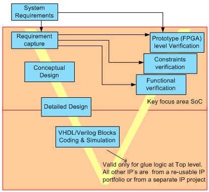
Figure 6 : Requirement based V&V
| Category | Remarks |
| Functional verification | 100% functional coverage at SoC level. Primarily simulation driven. Reuse of IP level verification item at SoC level |
| Constraints verification | Verify the SoC level constraints (e.g. area, power, timing etc.) Simulation plus review |
| Prototype validation | Primary vehicle for validating system level requirement at pre-silicon level. Also for HW-SW co verification and validation |
| Review/Audit | Checklist based review at every formal project gate level |
Table 3 : verification category
CHANGE REQUEST AND PROBLEM REPORT
Here we may use any standard tools that can support, track, and manage the process. However tools that can report the process status at a regular basis would be preferred. CollabNet TeamForge[4] offer one such tool, and this is what been used in our project. As we can see from the figure, the tool can report history information on the change request and problem report along with process maturity index. This will be helpful in assessing the process/product maturity at various project stages.
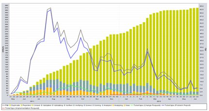
Figure 7 : Product maturity index
CONFIGURATION MANAGEMENT:
One of the important aspects of configuration management is the management of design and verification data throughout the life of the product including design in and customer support. Hence, there is a need for an effective recording and configuration management system. There are several interrelated aspects to configuration management. The primary requirement is a consistent repository of data. This repository contains identification of the design environment, a collection of design artifacts sufficient for consistent replication, and verification data that provides sufficient evidence that the design meets its requirements. Information in this repository needs to be maintained such that controlled changes preserve a consistent set of data.
TOOLS AND INFRASTRUCTURETool assessment is an important step to make sure that hardware design and verification perform correctly; those chosen must be, of course, suitability of the tool for their intended tasks and specified so that the process is traceable and repeatable. Apart from this the infrastructure also plays a bigger role in maintaining data integrity and maintainability. An early assessment of the tools used along with periodic planned review and audit is necessary to make sure about the data base integrity and correct transformation of the requirement to the product transition stage. The following are the typical elements that need to be reviewed and assessed within a project.
- Data base structure
- Development standards & flows
- Requirement management tools
- Configuration management tools and structure
- CR/PR system and tracking methodology
- Effective simulation analysis and regression systems
- Effective problem analysis and debug. For example automation in simulation/synthesis etc.
- Communication infrastructure between architects, design engineers, & verification engineers
- Documentation templates, location & traceability to make sure that all the team members get right information at right time
- Periodic audits (at least at each gate level) on all of the above
DESIGN ASSURANCE
Design assurance is an integral part of all the activities mentioned above. At a formal level the design team along with the quality assurance officer will analyze the following critical aspects at appropriate gate/milestone
- Formal reviews & audits of all artifacts.
- IP Vendor & IP quality checklist (IP reuse & IP intake strategy )
- Technology Library
- Process Reliability measures
- Data base (CM, CR/PR, Documentation)
- Compliance check against requirement specification/Implementation/Verification
- Verification strategy/methodology review
- Verification coverage review
- Explicit SoC constraints review
- Non functional requirement review (coverage)
- Layout review
CONCLUSION
A first time right development of any SoC requires a well defined development methodology that can effectively track the requirements, assess the risk at appropriate level and ensure process and product quality assurance across the product life cycle. Right information at right time at all level is the key for first time success
REFERENCE
[1] RTCA, 2000, DO-254: Design Assurance guidance for Airborne Electronic Hardware,
RTCA, Inc., Washington, DC.
[2] Telelogic DOORS. http://www.telelogic.com/products/doorsers/doors/ . http://www-01.ibm.com/software/awdtools/doors/
[3] http://www.magillem.com/
[4] http://www.collab.net/products/teamforge
Related Semiconductor IP
- NPU IP Core for Mobile
- NPU IP Core for Edge
- Specialized Video Processing NPU IP
- HYPERBUS™ Memory Controller
- AV1 Video Encoder IP
Related White Papers
- Efficient methodology for verification of Dynamic Frequency Scaling of clocks in SoC
- Methodology improves SoC power grids
- Unified Methodology for Effective Correlation of SoC Power Estimation and Signoff
- Safety Verification and Optimization of Automotive Ethernet Using Dedicated SoC FIT Rates
Latest White Papers
- Ramping Up Open-Source RISC-V Cores: Assessing the Energy Efficiency of Superscalar, Out-of-Order Execution
- Transition Fixes in 3nm Multi-Voltage SoC Design
- CXL Topology-Aware and Expander-Driven Prefetching: Unlocking SSD Performance
- Breaking the Memory Bandwidth Boundary. GDDR7 IP Design Challenges & Solutions
- Automating NoC Design to Tackle Rising SoC Complexity