CRAFT: Characterizing and Root-Causing Fault Injection Threats at Pre-Silicon
By Arsalan Ali Malik, Harshvadan Mihir, and Aydin Aysu
Department of Electrical and Computer Engineering, North Carolina State University, Raleigh, NC, 27695
Abstract
Fault injection attacks represent a class of threats that can compromise embedded systems across multiple layers of abstraction, such as system software, instruction set architecture (ISA), microarchitecture, and physical implementation. Early detection of these vulnerabilities and understanding their root causes, along with their propagation from the physical layer to the system software, is critical to secure the cyberinfrastructure. This work presents a comprehensive methodology for conducting controlled fault injection attacks at the pre-silicon level and an analysis of the underlying system for root-causing behavior. As the driving application, we use the clock glitch attacks in AI/ML applications for critical misclassification. Our study aims to characterize and diagnose the impact of faults within the RISC-V instruction set and pipeline stages, while tracing fault propagation from the circuit level to the AI/ML application software. This analysis resulted in discovering two new vulnerabilities through controlled clock glitch parameters. First, we reveal a novel method for causing instruction skips, thereby preventing the loading of critical values from memory. This can cause disruption and affect program continuity and correctness. Second, we demonstrate an attack that converts legal instructions into illegal ones, thereby diverting control flow in a manner exploitable by attackers. Our work underscores the complexity of fault injection attack exploits and emphasizes the importance of preemptive security analysis.
Keywords:
Fault injection attack; RISC-V; Instruction decode failure; Clock glitch; Pre-silicon
I. Introduction
Fault injection attacks (FIAs) deliberately introduce faults into a system to alter its behavior, exploiting, e.g., timing characteristics of designs to induce malfunctions. An attacker may be driven by various goals, such as (a) bypassing security mechanisms to gain unauthorized access to sensitive resources in PIN-based access controls [1]; (b) extracting secret keys by inducing faults during cryptographic operations [2]; (c) disrupting critical system functionality, causing failures in applications ranging from industrial control systems to IoT devices [3]; (d) escalating privileges within embedded systems, enabling unauthorized execution of commands or access to restricted data [4], and (e) targeting data integrity by introducing errors into computation/data flow, compromising the reliability and accuracy of critical systems [5, 6].
Pre-silicon analysis identifies vulnerabilities early in the design cycle, enabling targeted security enhancements before fabrication. Whereas, post-silicon verification ensures practical system resilience by validating countermeasures under real-world conditions. While prior works inject faults [7] or mitigate them by addressing symptoms [8], little research identifies the root causes of FIA vulnerabilities across pre- and post-silicon stages.
A key limitation of these works is their emphasis on analyzing the effects of faults, such as instruction skips or data corruption, while providing insufficient attention to investigating the underlying causes of fault generation. Understanding why these faults occur across multiple layers, such as instruction set architecture (ISA), microarchitecture, and physical hardware, remains critical to designing more effective, targeted countermeasures and uncovering undocumented and novel exploits.
In this work, we perform a clock glitch attack on the RISC-V soft-core processor, leveraging insights from pre-silicon analysis to systematically guide the post-silicon attack process. A clock glitch is a prevalent type of FIA, which alters the clock signal to disrupt the system’s state transitions and induces errors through timing violations [9, 7]. These attacks are often inexpensive, require minimal equipment, and can even be conducted remotely [10, 11]. Our key contributions include:
- RISC-V instruction characterization. We analyze and rank eight fundamental instructions in the RISC-V ISA based on their vulnerability at each pipeline stage.
- Identification of vulnerability cases. We identify four distinct cases where an attacker can maliciously redirect program flow through precise glitch configurations, allowing the conversion of a legal instruction in the RISC-V pipeline into an illegal one. These scenarios include:
- A novel approach to inducing instruction skips during critical operations, such as loading essential values from memory.
- Instances of silent corruption caused by the glitch, where the RISC-V processor remains unaware of the fault and fails to trigger an exception handler.
- Root-cause analysis and verification. Through systematic analysis of RISC-V RTL code and pre- and post-silicon verification, we identified and root-caused a previously unreported vulnerability in the pipeline registers shared among the Fetch (IF) and Decode (ID) stages.
This work advances the understanding of RISC-V soft-core processor reliability under clock glitch attacks by inducing instruction skips and identifying silent corruption. Our root-cause analysis and verification pave the way for developing stronger and lower-cost defenses to protect RISC-V systems.
II. Background
II-A. The Research Gap
Although a growing body of research has aimed to analyze and mitigate these threats [12, 7, 10], two critical limitations persist for clock glitch attacks. First, these works either focus on pre-silicon [13, 14] or post-silicon [15, 16, 11, 17] but rarely on both [18, 19]. It is critical to do both because pre-silicon analysis helps simulate internal intricacies and identify root causes, while post-silicon validation ensures that the found vulnerabilities does exist in the finished product. For example, post-silicon characterization [15] can identify the effects of the faults and the attack parameters needed to achieve these effects, but it cannot identify which paths in the circuit are causing these faults, which are needed to build low-overhead defenses or eliminate issues in the current design.
The closest works to our proposal conduct both pre- and post-silicon fault characterization of RISC-V and MSP430 ISA, respectively [18, 19]. Kazemi et al. conducted pre-silicon analysis using a C++ cycle-accurate model of processor behavior, which limits them to certain standard libraries and high-level functions. By contrast, our work identifies and tracks the traversal of faults from critical circuit elements to the application layer. FaultDetective investigates hardware-level faults by observing their manifested effects at the software level [19]. However, it relies on a redundant microcontroller design in lock-step1 and requires scan registers to observe internal states, limiting its scope and applicability.
II-B. Impact of Clock Glitch
A clock glitch attack involves a deliberate and temporary disruption of the clock signal, causing a misalignment between clock edges and corruption of the data being processed. In such an attack, an adversary introduces a brief pulse or delay into the clock signal, processing data earlier or later than intended. This timing disturbance can range from benign data misalignment to severe outcomes, such as data corruption or system control failures [15]. Our experiments on the RISC-V softcore processor demonstrate how attackers exploit these vulnerabilities to disrupt operations, induce data corruption, or create illegal states (see § III and IV).
Two critical parameters define the nature of a clock glitch: glitch offset and glitch width [15]. These parameters determine how the glitch affects the system’s timing and functionality [2].
Glitch offset (Toffset) defines the point in the clock cycle where the glitch is introduced, as shown in Fig. 1. A glitch occurring near the rising or falling edge of the clock can delay or advance transitions, misaligning data latching and clock edges. Depending on the timing, this disruption may affect different parts of the circuit, leading to data corruption in registers or incorrect state transitions.
Glitch width (Twidth) describes the duration of the clock disruption, as illustrated in Fig. 1. In clock glitching, reducing the glitch width increases the intensity of the fault2. The duration of the glitch influences how long the circuit remains unstable or misaligned, potentially causing errors such as intermediate values being incorrectly stored in registers. While longer glitches increase the likelihood of unintended behavior, not all glitch settings necessarily lead to data corruption.
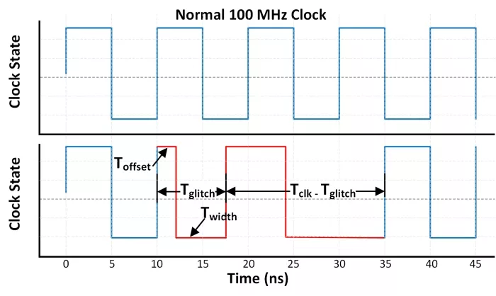
Figure 1: Illustration of a 100 MHz clock and a clock with a glitch. The top graph shows the regular clock signal with a stable period of 10 ns, while the bottom graph illustrates a clock glitch, where the positive edge is advanced, resulting in a shortened clock period. This disruption can lead to timing violations and data corruption in digital circuits.
II-C. Threat Model
We follow the conventional assumption in clock glitch attacks [5, 20, 8, 21, 2, 15]. Specifically, we assume that the attacker has physical access to the circuit’s clock signal, enabling the introduction of glitches with varying widths and offsets. The attacker aims to insert these glitches during critical operations to disrupt normal program control flow and induce data corruption or system misbehavior. By leveraging a phase-locked loop (PLL) [11], the attacker can dynamically generate and modify glitch parameters, allowing for precise manipulation of the clock signal during runtime. While we assume in-person manipulation, a sophisticated attacker may also tune these parameters remotely and dynamically, further heightening the risk of such attacks.
III. Fault Injection in RISC-V Processor
Prior works predominantly evaluate cryptographic software vulnerabilities using fault sensitivity analysis on specific applications like the final round of AES encryption, mostly through post-silicon experiments [15, 2]. By contrast, our approach integrates pre-silicon analysis with post-silicon validation to reveal vulnerabilities in RISC-V processor. First, we analyze instruction-level vulnerability across pipeline stages to identify potential attack vectors holistically. Second, we pinpoint the attack points of instructions via pre-silicon analysis. Lastly, we validate the alignment of pre- and post-silicon insights.
III-A. Fault Injection Methodology
To evaluate the effectiveness of the clock glitch attack on the RISC-V processor, we selected an embedded neural network inference code as a test case [22], which we compiled to relevant assembly code using the RISC-V toolchain.
Given the broad set of instructions in the RISC-V ISA, we focused our analysis on eight instructions that were particularly relevant to the test case3, e.g., the loop-trip count check in the softmax layer, which translates to a branch instruction in the RISC-V ISA, reading or writing weights or biases from memory using load and store instructions, respectively.
TABLE I: Risk assessment table (RAT) illustrating the total Faults Observed and Vulnerability Rankings (in Parentheses) Across Pipeline Stages, with 1 being the Least Vulnerable and 8 being the Most Vulnerable Instruction.
| Instruction | Total Faults Observed (Rank) | ||
| IF/ID | ID/EX | EX/WB | |
| c.addi | 1(2) | 13(5) | 16(6) |
| auipc | 0(1) | 0(1) | 5(3) |
| jal | 37(5) | 33(8) | 17(7) |
| bne | 6(4) | 4(3) | 8(5) |
| bge | 4(3) | 15(6) | 3(2) |
| c.lwsp | 4(3) | 2(2) | 7(4) |
| c.mv | 0(1) | 2(2) | 0(1) |
| lw | 28(6) | 23(7) | 20(8) |
Inducing timing violations with clock glitches involves strategically inserting a glitch at the precise moment. The glitch disrupts and violates the critical timing path of the targeted instruction, causing execution errors. To test this, we designed experiments targeting each instruction as it passes through individual pipeline stages. This approach aimed to achieve three objectives: (1) identify the timing path associated with each instruction in each pipeline stage; (2) determine the vulnerability of each instruction at each pipeline stage; and (3) minimize the search space for post-silicon validation by identifying glitch parameters that resulted in critical faults. For each instruction, we utilized 172 distinct clock glitch configurations, varying the offset (Toffset) and width (Twidth) of the glitch between 0.278ns and 8.89ns, with a step size of 0.5ns4. These configurations were small enough to induce precise timing violations and maintain efficiency in conducting numerous fault injection experiments.
A total of 9248 experiments were conducted (172 configurations × 4 pipeline stages × 8 instructions). These experiments allowed us to determine (1) the exact timing path of each instruction to induce a timing violation, (2) which instructions were vulnerable and at which pipeline stages, and (3) what the impacts of glitches on these instructions are. This analysis reduced the initial 9248 glitch configurations to 248, resulting in a reduction of 97.31%.
Critical fault. During our experiments, we observed eight distinct categories of fault behavior. However, we only focused on critical faults. In our work, we define a fault to be critical if it manifests in one of the following ways:
- Instruction skip. The instruction is either skipped entirely or its result is corrupted, e.g., for a load instruction, its old value is retained, or a new corrupted value is stored in the destination register when the instruction is retired.
- PC redirection. The PC is redirected to an incorrect address, thereby disrupting program flow, e.g., in the case of a jump instruction, the next PC value is computed by summing the current PC value with an immediate offset. A corruption in either of these values leads to faults in subsequent PC calculations.
- Non-critical fault. Clock glitches are known to freeze the CPU, suspending it in an undefined state [23]. Recovery from this state often requires a CPU reset. We classify such faults as non-critical in terms of their limited application. Such faults are beyond this study’s scope and thus not explored further.
Table I presents the selected eight instructions and the resulting risk assessment table (RAT) categorizing critical faults. The RAT has utility for both attackers, who can use it to identify the vulnerable instructions in respective pipeline stages, and for system designers aiming to secure their implementations by addressing the vulnerabilities identified in the RAT. The table lists the total number of critical faults observed. It also assigns vulnerability ranks to each instruction, with a higher rank indicating greater vulnerability to clock glitches5.
We utilized the RAT ranking to hypothesize the causes of the faults and validated this hypothesis through our systematic methodology, as elaborated in the next section.
III-B. Root-Cause of Failure
To analyze the origins of critical faults, we consulted the RISC-V instruction set manual [24]. Fig. 2 shows the instruction format for RISC-V ISA. The format consists of an opcode, a destination register, source registers, and, depending on the instruction type, either a sub-function (for R-type instructions) or an immediate (imm) field (for I-type instructions). A clock glitch that corrupts this format can have four possible outcomes: Ⓐ altering the opcode to execute an unintended instruction, causing incorrect system behavior; Ⓑ corrupting the destination register, leading to incorrect data storage; Ⓒ corrupting source registers, causing data to be fetched from incorrect locations; or Ⓓ affecting the sub-function or immediate fields, resulting in incorrect operation execution or erroneous PC calculations.
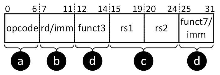
Figure 2: RISC-V instruction format depicting the opcode, register fields, function codes, and immediate values, highlighting the utilization of various fields depending on the instruction type, e.g., R-type, I-type. Corruption in different fields of instruction can lead to distinct behaviors.
To better understand this scenario, consider an example involving the RISC-V processor. Fig. 3 illustrates the RISC-V processor pipeline suffering from a clock glitch attack. At every clock cycle, the PC points to the memory address containing the next instruction to fetch. The fetched instruction is stored in the IF/ID pipeline register6 which is shared between the fetch (IF) and the decode (ID) stage (shown as IF/ID in Fig. 3). Consider the scenario where the PC reaches the value of 0xB5E, and an ‘AND’ instruction is fetched. A precise clock glitch corrupts the instruction stored in the IF/ID pipeline register—our technique in Section III-A has identified this is an instruction that can be corrupted between the IF and the ID stage without corrupting other pipeline stages.
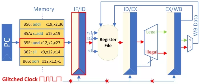
Figure 3: Visualization of the CV32e40x 4-stage pipeline processor. In the Fetch stage, when the program counter loads the ‘and’ instruction from memory, a clock glitch disrupts the operation, corrupting the pipeline registers shared between the Fetch and Decode stages, resulting in the misclassification of the legal ‘and’ instruction as an illegal instruction.
Once an instruction reaches the decode-execute (ID/EX) junction, if the instruction conforms to the RISC-V instruction format rules, it proceeds to further execution; otherwise, it is flushed from the pipeline. This flush skips the ‘illegal’ instruction, and the PC advances to the next valid instruction. The RISC-V ISA classifies such invalid instructions as ‘illegal.’ In this example, the clock glitch corrupted the fetched ‘AND’ instruction, causing it to be misclassified as ‘illegal’ and subsequently skipped. As a result, no valid value is written to the destination register associated with the ‘AND’ instruction.
The RISC-V instruction set manual specifies conditions for flagging illegal instructions but does not prescribe explicit corrective actions, instead recommending that instructions must always remain valid. This lack of guidance places the burden of implementing exception handling on the user. Our analysis of the RISC-V source code showed that the inserted clock glitch corrupted the IF/ID pipeline register. This register, named if_id_pipe_o in the source code, is driven by a long combinational path. The glitch caused a timing violation, corrupting its contents. It holds the fetched instruction and its control signals, passing them to the ID stage for decoding. This register ensures the correct instruction flow and maintains synchronization within the pipeline.
Fig. 4 illustrates the critical path we identified through pre-silicon and source code analysis. Consider a jump (‘JAL’) instruction that flows through this path. The ‘JAL’ instruction computes the new target PC by summing the current PC value of the decode stage (‘pc_id’) with an immediate value (‘imm_uj_type’) provided by the if_id_pipe_o register. The if_id_pipe_o register derives its input from the ‘compressed decoder’ module, which handles RISC-V’s compressed instruction set extension, converting 16-bit compressed instructions into their 32-bit equivalents. A clock glitch corrupts the input flowing into the ‘compressed decoder,’ resulting in an incorrect format being stored in if_id_pipe_o. This ultimately affects the ‘imm_u_type’ field and leads to incorrect PC calculations, causing the processor to jump to an incorrect address. The incorrect PC value causes the instruction to be classified as ‘illegal’. Without an exception handler, the processor skips the illegal instruction to resolve the error.
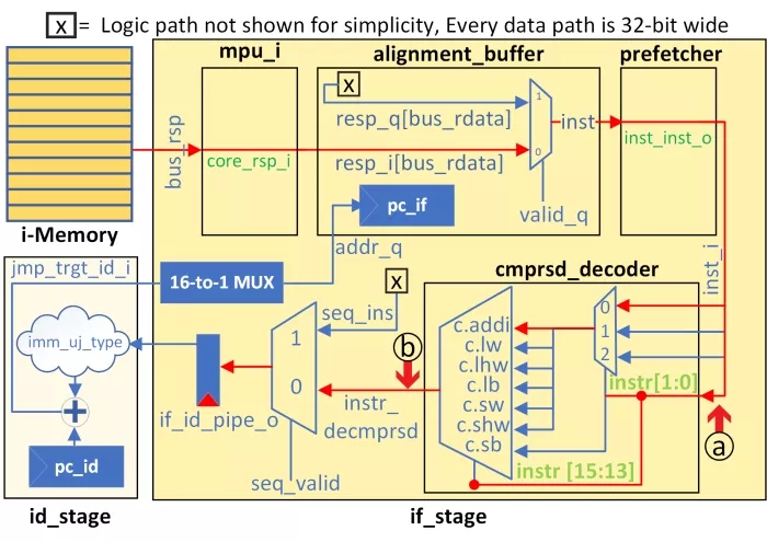
Figure 4: The root cause of failure in the CV32e40x processor. A clock glitch disrupts the long combinational logic path, causing the input to the compressed decoder module to be latched prematurely (see ⓐ). This leads to misclassifying legal instructions as illegal in subsequent clock cycles.
III-C. Crafting the Proposed Attack
Building on insights from § III-A and III-B, we identified the timing parameters required to induce timing violations from RAT and the critical paths susceptible to clock glitches through root-cause analysis. RAT also helped us identify load (lw) and jump (jal) as the most vulnerable instructions. Therefore, we refined the clock glitch parameters with our prime focus being these two instructions, resulting in our proposed attack. By further tuning these parameters, we discovered two additional ranges that an attacker could utilize to either skip specific instructions or redirect the program flow without raising an ‘illegal’ instruction flag (refer § IV for details on the parameters). This allows sophisticated attackers to cause significant disruptions while leaving the processor unaware of the corruption.
Expected outcomes of the our attack are outlined below:
- Case #1: The instruction is skipped, triggering the ‘illegal’ flag and the exception handler.
- Case #2: The destination register (‘rd’) is zeroed while triggering the ‘illegal’ flag and the exception handler.
- Case #3: The destination register (‘rd’) is zeroed without triggering the ‘illegal’ flag or the exception handler.
- Case #4: The destination register (‘rd’) is partially corrupted without triggering the ‘illegal’ flag or the exception handler.
In Case #1 and Case #2, the ‘illegal’ flag triggers an exception, which redirects the program to the address of the exception handler. If no exception handler is defined, the program simply skips the instruction and continues execution. By contrast, the ‘illegal’ instruction flag is not even triggered in Case #3 and Case #4. This is because in these cases, the input to the ‘compressed decoder’ is latched just in time, avoiding detection as an ‘illegal’ instruction (refer ⓐ in Fig. 4). However, the output of the ‘compressed decoder’ still fails to meet timing constraints (refer ⓑ in Fig. 4). Table II summarizes the parameter ranges for testing and evaluating the proposed attack. This failure results in the register writes of the targeted instruction being either (a) zeroized or (b) partially corrupted, without triggering the ‘illegal’ flag during execution. Consequently, the processor remains unaware of the silent fault. Such vulnerabilities pose significant risks to critical applications, including neural networks. A well-timed attack could silently corrupt crucial operations, such as loading weights or biases from memory, potentially leading to undetectable critical misclassifications.
IV. Pre-Silicon and Post-Silicon Results
Test-Platform. We used the Vivado 2020.2 and the CV32e40x soft-core processor for the pre-silicon instrumentation. As part of our case study, we explored the impact of clock glitch-based fault injections on a neural network algorithm running inferences for the MNIST dataset [22]. We ran the RISC-V processor at 50 MHz with a timing constraint of 20ns specified in the constraint (*.xdc) file.
TABLE II: Experimental results showing various glitch offset and width configurations that lead to output corruption. Adjusting the glitch width produces effects such as instruction skipping, loading all zeroes, or selective corruption of the MSBs.
| Case # |
Toffset (ns) |
Twidth (ns) |
Tglitch (ns) |
Illegal Flag Raised |
Effect Observed |
|---|---|---|---|---|---|
| 1 | 0.833 | ≤2.967 | ≤3.8 | ✓ | Instruction Skip |
| 2 | 3.067 – 3.567 | 3.901 – 4.400 | ✓ | Data Zeroization | |
| 3 | 3.667 – 4.289 | 4.504 – 5.121 | ✗ | Data Zeroization | |
| 4 | 4.289 – 4.339 | 5.112 – 5.172 | ✗ | Partial Data Corruption |
We deployed the CV32e40x soft-core processor on the Xilinx Kintex-7 XC7K160T FPGA platform for post-silicon verification. Using the RISC-V compiler toolchain we generated the binary file of the inference code, comprising the necessary machine instructions and associated data. A custom controller module was developed to enable data transmission from the host PC to the FPGA. We used the FPGA’s internal PLL to introduce glitches to the clock signal. When the processor core detects the target instruction, it relays a trigger signal to the glitch circuitry, as depicted in Fig. 5. The PLL generates three distinct clock signals: ‘CLK0’, which serves as the reference base clock at 50 MHz, ‘CLK1’ and ‘CLK2’, which are phase-shifted versions of ‘CLK0’. We can modulate the glitch parameters by dynamically reconfiguring the phase difference among these clocks. The phase difference of ‘CLK1’ relative to ‘CLK0’ and ‘CLK2’ defines Toffset and Twidth, respectively. To investigate clock glitches effect, we integrated the internal logic analyzer (ILA) into our design to capture, observe, and analyze core signals, such as, the PC value, register file contents, and critical control signals [25]. The ILA monitored and sampled these signals at 300 MHz frequency, the maximum reliable limit for our target hardware7.
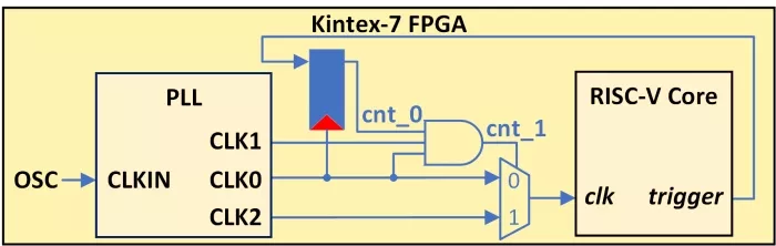
Figure 5: Circuit diagram of the clock glitch injection setup using three PLL-generated clocks to tune glitch parameters. A core trigger signal and intermediate signals vary glitch position and timing.
IV-A. Pre-Silicon Verification
We used gate-level post-synthesis netlist to orchestrate our attack and inject faults for two reasons: (i) it is the earliest design stage that includes the circuit’s timing information. Analysis at this stage allows for identifying potential vulnerabilities and timing-related issues that could be challenging and costly to address later in the design process, and (ii) it enables rapid and detailed analysis with minimal overhead compared to post-silicon evaluations. Fig. 6(a) and (b) present a snippet of the C code and the corresponding assembly code of the inference algorithm, respectively. The attack target is the ‘lw’ instruction with a PC value of 0x386.
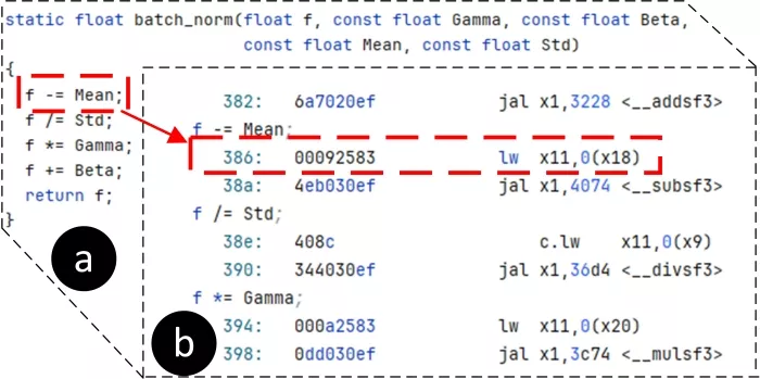
Figure 6:(a) C-code for MNIST inference and (b) the targeted ‘load’ instruction in the assembly by the proposed attack.
We induced timing violations by injecting glitches into the nominal clock, adjusting Toffset and Twidth to ensure that the data does not reach the if_id_pipe_o register in time for the next clock edge. Fig. 7(a) shows fault-free execution of the neural network inference model (without clock glitch). A 64-bit counter increments with each rising clock edge to mark time progression. At clock cycle 1197, the ‘lw’ instruction is fetched with a PC value of 0x386. In a fault-free execution, the instruction completes when the counter reaches 1201, loading the value 0x42026ada into the register ‘x11’, as shown in red.
Fig. 7(b) shows the first-order effect of the clock glitch (red ellipses), showing zeroization of register ‘x11’ associated with the ‘lw’ instruction as expected in Case #2 and Case #3. It also depicts the second-order effect (marked in yellow rectangles), where the immediate value in the ‘JAL’ instruction is corrupted, resulting in incorrect ‘pc_if’ redirection. Normally, ‘JAL’ correctly redirects ‘pc_if’ to offset 0x4074, as shown in Fig. 6(b) and 7(a). Through our proposed work, however, ‘pc_if’ is incorrectly redirected to 0xF3698 due to premature latching in the ‘compressed decoder’ module, as explained in § III-C, causing cascading faults in the program flow.
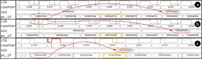
Figure 7: Our proposed work targetting the RISC-V ISA in a neural network inference algorithm [22] is depicted in three scenarios: (a) without and with a clock glitch in (b) pre- and (c) post-silicon. The first-order effect of the clock glitch attack corrupts the destination register ‘x11’ associated with the ‘lw’ instruction, loading all zeroes. The second-order effect corrupts the immediate field of the ‘JAL’ instruction, disrupting the normal program flow and causing incorrect control flow redirection. In (c), the glitched clock signal is drawn by hand due to the limited sampling capacity of the integrated logic analyzer.
IV-B. Post-Silicon Verification
We were able to successfully reproduce similar effects at the post-silicon level for Case #1, Case #3, and Case #4. Fig. 7(c) illustrates the verification results for Case #1, where the attacked load instruction at the PC value 0x386 is skipped (highlighted in red ellipse), raising the illegal instruction flag. The glitched clock signal is drawn by hand due to the limited sampling capacity of the ILA. The glitched clock experiences rapid transitions from low↔high within 0.833ns, significantly shorter than the ILA’s sampling period of 3.33ns, resulting in undersampling of the glitch transitions.
For Case #2, the fault effects differ between pre-silicon and post-silicon experiments. The ‘x11’ register loaded non-zero values during post-silicon verification versus all zeroes in pre-silicon. We speculate that the clock glitch that the prematurely latched input to the ‘compressed decoder’ differs between pre-silicon and post-silicon results. This input consisting of the fetched instruction dictates the final value written to the ‘x11’ register as explained in § III-B. Also, the fetched PC gets redirected to 0xFFF337A4 instead of 0xF3698, as shown in Fig.7(b). Although the glitch effects are similar for the same settings, we speculate that the differences in corrupted values arise from critical path delay variations between post-synthesis and place-and-route netlists. We confirmed the existence of silent faults for Case #3 and Case #4 in post-silicon.
V. Acknowledgements
This work is funded in part by the Office of Naval Research (ONR) grant N00014-23-1-2103. The views, opinions and/or findings expressed are those of the authors and should not be interpreted as representing the official views or policies of the Department of Defense or the U.S. Government. Approved for public release. Distribution is unlimited.
VI. Conclusion
This work uncovers critical vulnerabilities in RISC-V softcore processors under clock glitch-based fault injection attacks, revealing vulnerabilities such as instruction skips, data corruption, and illegal control flow execution. Our pre-silicon fault analysis of the CV32e40x pipeline ranks instructions based on their susceptibility at various pipeline stages. Our findings highlight pivotal attack vectors and emphasize the importance of pre- and post-silicon validation, stricter timing constraints, and improved exception handling. Future research could extend these techniques to other architectures, with an emphasis on developing automated, dynamic countermeasures.
References
[1] K. Murdock, D. Oswald, F. D. Garcia, J. Van Bulck, D. Gruss, and F. Piessens, “Plundervolt: Software-based fault injection attacks against Intel SGX,” in IEEE Symposium on Security and Privacy, 2020.
[2] B. Yuce, P. Schaumont, and M. Witteman, “Fault attacks on secure embedded software: Threats, design, and evaluation,” Journal of Hardware and Systems Security, vol. 2, pp. 111–130, 2018.
[3] M. Gabrick, R. Nicholson, F. Winters, B. Young, and J. Patton, “FPGA considerations for automotive applications,” Tech. Rep., 2006.
[4] O. Mutlu and J. S. Kim, “Rowhammer: A retrospective,” IEEE Transactions on Computer-Aided Design of Integrated Circuits and Systems, vol. 39, no. 8, pp. 1555–1571, 2019.
[5] T. Chamelot, D. Couroussé, and K. Heydemann, “SCI-FI: control signal, code, and control flow integrity against fault injection attacks,” in IEEE Design, Automation & Test in Europe Conference & Exhibition, 2022.
[6] C. Gongye and Y. Fei, “One Flip Away from Chaos: Unraveling Single Points of Failure in Quantized DNNs,” in IEEE International Symposium on Hardware Oriented Security and Trust. IEEE, 2024, pp. 332–342.
[7] A. M. Shuvo, T. Zhang, F. Farahmandi, and M. Tehranipoor, “A comprehensive survey on non-invasive fault injection attacks,” Cryptology ePrint Archive, 2023.
[8] P. Nasahl and S. Mangard, “SCRAMBLE-CFI: Mitigating Fault-Induced Control-Flow Attacks on OpenTitan,” in Proceedings of the Great Lakes Symposium on VLSI 2023, 2023, pp. 45–50.
[9] A. Gangolli, Q. H. Mahmoud, and A. Azim, “A systematic review of fault injection attacks on IOT systems,” Electronics, vol. 11, 2022.
[10] J. Zhang and G. Qu, “Recent attacks and defenses on FPGA-based systems,” ACM Transactions on Reconfigurable Technology and Systems (TRETS), vol. 12, no. 3, pp. 1–24, 2019.
[11] L. Antoni, R. Leveugle, and B. Fehér, “Using run-time reconfiguration for fault injection applications,” IEEE Transactions on Instrumentation and Measurement, vol. 52, no. 5, pp. 1468–1473, 2003.
[12] I. Verbauwhede, D. Karaklajic, and J.-M. Schmidt, “The Fault Attack Jungle - A Classification Model to Guide You,” in 2011 Workshop on Fault Diagnosis and Tolerance in Cryptography, 2011, pp. 3–8.
[13] P.-Y. Péneau, L. Claudepierre, D. Hardy, and E. Rohou, “NOP-Oriented Programming: Should we Care?” in 2020 IEEE European Symposium on Security and Privacy Workshops (EuroS&PW). IEEE, 2020.
[14] J. Grycel and P. Schaumont, “Simplifi: hardware simulation of embedded software fault attacks,” Cryptography, vol. 5, no. 2, p. 15, 2021.
[15] B. Yuce, N. F. Ghalaty, and P. Schaumont, “Improving fault attacks on embedded software using RISC pipeline characterization,” in Workshop on Fault Diagnosis and Tolerance in Cryptography. IEEE, 2015.
[16] Z. Kazemi et al., “On a low cost fault injection framework for security assessment of cyber-physical systems: Clock glitch attacks,” in IEEE 4th International Verification and Security Workshop, 2019.
[17] B. Yuce, N. Ghalaty, H. Santapuri, C. Deshpande, and P. Schaumont, “Software Fault Resistance is Futile: Effective Single-Glitch Attacks,” in Workshop on Fault Diagnosis and Tolerance in Cryptography, 2016.
[18] Z. Kazemi, A. Norollah et al., “An in-depth vulnerability analysis of risc-v micro-architecture against fault injection attack,” in 2021 IEEE International Symposium on Defect and Fault Tolerance in VLSI and Nanotechnology Systems, 2021.
[19] Z. Liu, D. Shanmugam, and P. Schaumont, “FaultDetective: Explainable to a Fault, from the Design Layout to the Software,” IACR Transactions on Cryptographic Hardware and Embedded Systems, 2024.
[20] P. Nasahl, M. Osorio, P. Vogel, M. Schaffner, T. Trippel, D. Rizzo, and S. Mangard, “SYNFI: pre-silicon fault analysis of an open-source secure element,” arXiv preprint arXiv:2205.04775, 2022.
[21] L. Claudepierre, P.-Y. Péneau, D. Hardy, and E. Rohou, “TRAITOR: a low-cost evaluation platform for multifault injection,” in International Symposium on Advanced Security on Software and Systems, 2021.
[22] B. McDanel, S. Teerapittayanon, and H. Kung, “Embedded binarized neural networks,” arXiv preprint arXiv:1709.02260, 2017.
[23] C. Spensky, A. Machiry et al., “Glitching Demystified: Analyzing Control-flow-based Glitching Attacks and Defenses,” in 51st IEEE/IFIP International Conference on Dependable Systems and Networks, 2021.
[24] A. Waterman, Y. Lee, D. A. Patterson, and K. Asanovic, “The RISC-V instruction set manual, volume I: User-level ISA, v2.0,” EECS Department, University of California, Berkeley, Tech, p. 4, 2014.
[25] UG908, Vivado Design Suite User Guide, “Programming and Debugging,” San Jose, CA, USA, 2023.
Related Semiconductor IP
- All-In-One RISC-V NPU
- ISO26262 ASIL-B/D Compliant 32-bit RISC-V Core
- RISC-V CPU IP
- Data Movement Engine - Best in class multi-core high-performance AI-enabled RISC-V Automotive CPU for ADAS, AVs and SDVs
- Low Power RISCV CPU IP
Related White Papers
- A Survey on SoC Security Verification Methods at the Pre-silicon Stage
- Reconfiguring Design -> Reconfigurable computing aims at signal processing
- Novel advances for embedded memory emerge at CICC
- Customized DSP -> Parallel DSPs: speed at a price
Latest White Papers
- Breaking the Memory Bandwidth Boundary. GDDR7 IP Design Challenges & Solutions
- Automating NoC Design to Tackle Rising SoC Complexity
- Memory Prefetching Evaluation of Scientific Applications on a Modern HPC Arm-Based Processor
- Nine Compelling Reasons Why Menta eFPGA Is Essential for Achieving True Crypto Agility in Your ASIC or SoC
- CSR Management: Life Beyond Spreadsheets