An UML-driven Interface Generation Approach for SoC Design
By André Aziz, Francielle Santos, Daniele Santos, Millena Almeida, Edna Barros
Informatics Center, Federal University of Pernambuco
Abstract:
In the latest years, the usage of UML to describe complete systems, including SoCs [1], has been increased. In trend with this line, this work proposes a methodology, based on UML, for SoCs designing which is focused on high-level communication modeling. The goal is to transform UML models, compliant with UML profile for SoC [2], into SystemC behavioral descriptions, which can be synthesized through EDA tools [3]. The methodology proposes a flow supported by an organizational development process [4], and a code generation tool.
1. INTRODUCTION
Nowadays, UML has been used to describe systems, not only software-based ones, but for general complex systems, whose parts can be implemented in hardware as well [1]. However, a lot of profiles have been developed, intending to match UML to systems designing needs. For System-on-Chip (SoC) design, UML has been accepted as next generation language [5], because of its capability to describe, at a high level, both architecture and communication. In order to obtain a description closer to implementation, a UML specification should be transformed into a hardware software specification language such SystemC. The synthesis of a UML description into a SystemC specification is a challenge and some works are able to do a translation between these two languages [6][7][8], but usually the generated code can not be synthesized by behavioral synthesis tools.
In this work, we propose a technique for generating synthesizable SystemC code from UML 2.0. Starting with system requirements specification, the proposed methodology defines steps to transform requirements into a set of models, which are compliant to UML profile for SoC [2], and a tool that automatically translates these models into a synthesizable code through a behavioral synthesis tool.
The proposed methodology allows designers to choose, at system level, which protocol could be used either by internal as well as by external modules interfaces. This feature is very helpful to speed up the system design and, combining it with the support for code generation, system designers can handle with communication abstract level describing it as simply function calls.
This work is part of an IP core development process (ipPROCESS [4]), which organizes the IP design flow as a set of activities in disciplines and workflows, guiding designers through the development. Each ipPROCESS set of activities, related to a certain area, is grouped into a discipline, according to the RMM [9] design flow. For instance, activities related to project specification are grouped into the Requirements discipline; activities related to functional verification are grouped into the Verification and so on.
Along this paper, methodology concepts will be illustrated through the design of a LCD Controller. This IP core controls a display that contains 32 (two lines of 16) characters of 5x8 or 5x7 bits and was developed in the context of the Brazil-IP Project [10].
This paper is divided as follows. Section 2 gives an state of the art overview. Section 3 summarizes the proposed methodology flow. Section 4 describes the proposed mechanism for functional architecture mapping. Section 5 provides a description of strategy for SystemC code generation. Section 6 illustrates the validation results, while Section 7 concludes the paper, listing potential improvements and future work.
2. RELATED WORKS
Many approaches and languages have been used to specify systems in the last years. However, UML has shaped up to be a better alternative to describe both communication and architecture together. Thus, various UML profiles (extensions to UML) have been developed to improve the UML models expression power. Specifically to IP and SoC modeling there are many ongoing works [2][5][6][7][8] that show how UML can be applied in this field.
The UML profile for SoC [2] is a profile defined by OMG [11] which adds the SoC description capability to UML. It supports hierarchical representation of modules and models information shared between them. In addition, this profile shows how to generate code from a model using its definitions. However, the profile does not make a reference about a tool that automatic generates code, or if this code could be synthesized.
Another work describes a SoC design methodology that uses a UML 2.0 profile for SystemC [6]. This work shows how UML can improve a conventional SoC design flow essentially in three ways: in a System Functional Model level; in a hardware description phase (before RTL) applying a profile for SystemC; in the software parts using profiles for Java, C++, etc. Also, this work demonstrates the translation from the proposed profile to SystemC code using state diagrams to capture the behavioral and class diagrams to hierarchical modeling. Nevertheless, this work does not make reference to a systematic way for mapping requirements into architecture.
3. METHODOLOGY FLOW
In order to design a system, first the requirements must be collected and analyzed. After that, they are transformed into architecture to be implemented. In most of the cases, it is not easy to transform requirements into a good architecture, or even to implement the proposed architecture. This way, the architecture proposition step is usually avoided in these cases.
To tackle this problem is proposed a modified methodology flow, which can be seen in Figure 1.
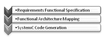
Figure 1. Methodology flow
The methodology focuses on the transition from the requirements to the implementation. The first step, represented by the requirements functional specification, is described in terms of use cases. A use case is composed by ordered steps (flow of events) that represent the functionality performed by the system from the user point of view. These concepts can be modeled in UML, as shown in Figure 2 that describes use cases for a LCD controller.
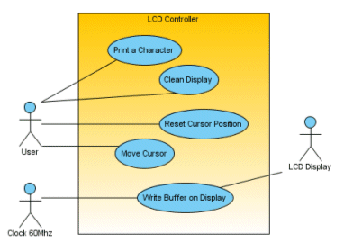
Figure 2. LCD Controller use cases
In this case, the LCD Controller is composed by five essentially functionalities: Print a Character, Clean Display, Reset Cursor Position, Move Cursor, and Write Buffer on Display. Additionally there are three relationships with external systems: User, Clock 60MHz, and LCD Display. Basically, this diagram shows what the system positive scope (use cases) is and what the negative scope (actors) is.
The second step consists in mapping the functional specification into architecture. We propose a well-defined workflow for accomplishing the mapping, so this task is done systematically and the results are expressed by a set of UML Models, compliant to UML profile for SoC. First of all, the main use cases are selected to be analyzed. During the analysis, for each use case, the elements models like classes, ports and protocols are identified, and the use case steps are organized into activity diagrams. So, the functionality flow is modeled through sequence diagrams, distributing the responsibilities among elements. After refining and unifying the diagrams, they can be reviewed to find reuse opportunities. Finally, the interfaces between architecture modules are designed at a very high abstraction level.
In the third step, having the system architecture, as a way of reducing the gap between architecture and implementation, the proposed methodology provides a tool that generates synthesizable code SystemC from the UML models previously designed. The generated code can be synthesized using a behavior synthesis tool [3].
3. FUNCTIONAL ARCHITECTURE MAPPING
To support the functional architecture mapping, the ipPROCESS provides an activity flow in one of its areas of concern called Analysis & Design discipline. This flow is showed in Figure 3.
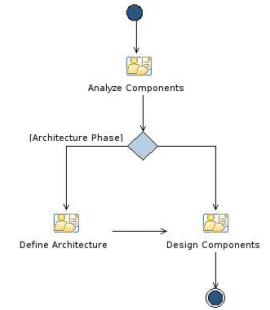
Figure 3. Functional architecture mapping by ipPROCESS
A more detailed description about the activities is given in the next sub-sections.
3.1 Analyze Components Activity
The first step is to select the main use cases to be analyzed. Due the increasing system complexity, this procedure can be very expensive, in terms of cost and time, if it would be applied to all functionalities. Some criteria used include the selection of the biggest or more complex use cases, which will help in the definition of stable architecture. Usually, how bigger the use case is, higher is the probability that it contains information about internal structure and external interfaces. Complex use cases probably present some restrictions, which the candidate architecture should comply.
In our example, Print a Character and Write Buffer on Display were chosen (see Figure 4). The first one was chosen due to its probability to manipulate data into a big set of internal elements. The other one has many relationships with external system, helping to define ports and protocols that our IP core should be complaint.
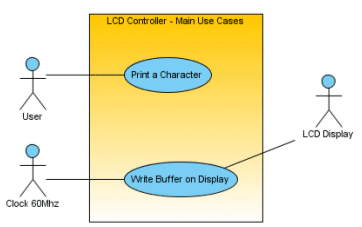
Figure 4. LCD Controller main use cases
Applying a guided textual analysis on each selected use case (see Figure 5), basic architecture elements can be found. Those elements are divided in two groups: elements that express data and elements that express control over data. The elements of the first group are usually expressed as nouns appearing in many use case steps or nouns transformed in others along the flow. The entities that manipulate the data, second group, are usually related to verbs that execute actions over the data or nouns that represents the idea of data storage like memories. Figure 6 shows the Print Character use case architecture elements.
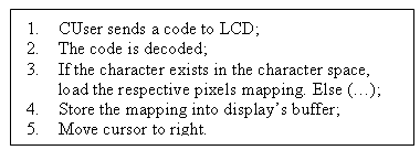
Figure 5. Print Character main flow

Figure 6. Identified basic elements
Upon identifying the basic elements (see Figure 6), the use case flows are analyzed, resulting a UML sequence diagram (see Figure 7) with classes (from basic elements) and theirs operations (from use case flows’ steps), with parameters and return (manipulated data). The timing information is also expressed by vertical axis of sequence diagram.
This way, the use cases’ flows are mapped into these diagrams, enabling the designers to achieve functional architecture mapping.
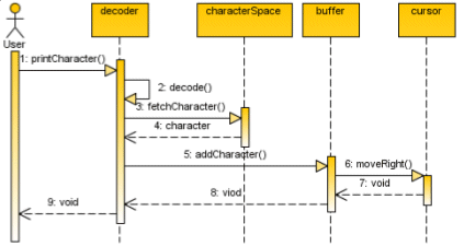
Figure 7. Sequence diagram for Print Character use case
3.2 Define Architecture Activity
Doing the steps described in the previous subsection to each selected use case, the resulting diagrams should be unified, representing a stable architecture model for implementing the complete system. During this step, it’s important to analyze: classes that have different names but similar behavior (can be unified), complex classes, with many different responsibilities (candidates to be split) and so on. By using design patterns or even by identifying reuse opportunities the architecture can be improved.
After this unifying, the classes must be transformed into modules that communicate through ports. To connect the classes, it is necessary to analyze the sequence diagrams identifying which class needs to communicate with other and build a connection between their ports.
At this point, we have an abstract architecture of the system. So we need to check if the unselected use cases are already represented in this model. If not, the model should be extended to support those functionalities. For our case study, the classes CursorControl and Cursor have been modified and organized in a single module Cursor as it can be seen in Figure 8.
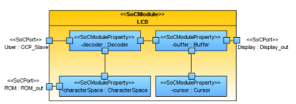
Figure 8. LCD Controller structural model
3.3 Design Components Activity
This activity consists in designing the communication protocols and functions between the internal and external modules. For each connection, the designer has to define a function interface and a protocol. Function interfaces, which are not defined by OMG’s profile, organize what functions will be available through that specific port, while protocol will define how data will be shared in that connection. Finally, we need to define what operations will be implemented as process (SoCProcess stereotype).
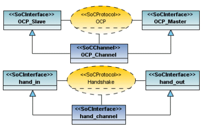
Figure 9. Collaborations for OCP and Handshake protocols used in LCD Controller
In accordance to UML profile for SoC, protocols are represented by collaboration that contains a channel and two interfaces. Figure 9 shows the collaboration for OCP and Handshake protocols.
The functional interface IDecoderCharacter, in the Figure 10, defines what functions port d, which realizes IDecoderCharacter, (of CharacterSpace module), should provide to port c, which uses IDecoderInterface, (of Decoder module).

Figure 10. Functional Interface example
After defining interfaces and protocols, we have the system final architecture, which is composed by a set of specific models: hierarchical, communication, and structural. Hierarchical models show the modules and sub-modules organization and their connections. Communication models include communication protocols between either internal as well as external modules. Structural models describe internal elements like processes, ports, and signals as is shown in Figure 8 and Figure 10.
4. SYSTEMC CODE GENERATION
Using the models elaborated along the functional architecture mapping as input to our tool, we can generate code that can be synthesizable by a commercial tool. The code generation is focused on the synthesis of inter-module interfaces, according to the chosen protocol. The primary goal of this tool is to allow designers to specify module communication as functions calls without worrying about protocol communication.
The tool analyzes all functions calls between modules and builds an abstract interface. This generated interface can be used by a designer to access functions in another module. To do this, the interface transforms the function call (including parameters) into a set of packages which are implementing the chosen protocol. When these packages arrive in the other side, they are reorganized and a function call is done. After that, the return value is sent back through the protocol to the function caller. Also, our tool provides monitors to evaluate communication cost of the system, helping the designer to analyze the time spent with communication and choose another protocol if necessary. The Figure 11 presents the tool’s flow.
Starting by the UML description, a XMI file [12] is generated by a UML parser. We are using XMI, due to the fact that it is a well-defined standard for sharing UML models between UML tools. So, this file is processed, hierarchy and communication of modules are extracted, and a virtual structure is built. After this, our tool generates all inter-module interfaces matching the chosen protocol with the function call needs. Finally, one monitor is exported for each interface.
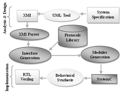
Figure 11. Tool`s flow
In the interface generation step, our strategy proposes a port model as showed in Figure 12. A SoCPort is composed by a SoCInterface related to chosen protocol and set of functions defined in Functional Interface. The SoCInterface is defined as a modular interface, and is already implemented in protocols library. In the other hand, the functional interface, which encompasses the SoCInterface, is automatically generated by the tool according to UML input model.
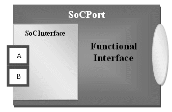
Figure 12. Port general structure
There are two kinds of functional interface: one to ports that realize an interface and other to ports that use an interface. In the first case, the interface reads data from SoCInterface and “calls” a function from the parent module. In the second case, the interface process functions called by parent module and writes data into SoCInterface.
It is important to notice when a module has a port which realizes an interface, it is necessary add some processes in the module to read data from the port and build the related function call. Our strategy supports also the generation of such modules. Below, we have summary of the code generated to example illustrated in Figure 10.
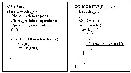
Figure 13. Summary of generated code in case of a port which uses an interface
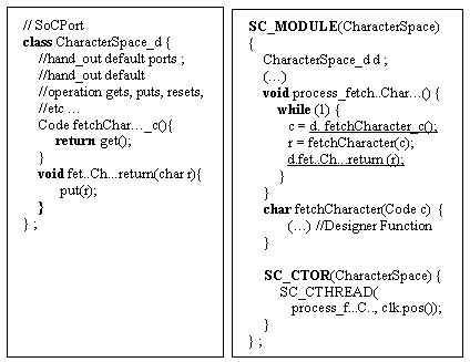
Figure 14. Summary of generated code in case of a port which realizes an interface
As Figure 13 presents, the designer of Decoder module can easily call fetchCharacter function of CharacterSpace module through c port (underlined function call). In Figure 14, the generated code shows that the process_fetchCharacter waits (blocked) until a new data be available on interface, this is performed by fetchCharacter_c function call. When data arrives on interface, the function unblocks the process. Thus, the process can make a call to the designer defined function (fetchCharacter) and, finally, returns the result through SoCInterface, calling fetchCharacter_return function.
5. RESULTS
We have applied this methodology in the development on MPEG-2 encoder. The generated code was compared to a code made by designers of Brazil-IP program [10]. Both implementations were synthesized by Cynthesizer Tool of Forte Design Systems [3] and the synthesis results are compared in terms of estimated area, number of code lines, bugs found, and clock frequency. The synthesized models were tested in Altera Cyclone II FPGA.
Table 1. Results of proposed approach X traditional design
| Designed Model | Generated Model | |
| Register Bits | 19357 | 23269 |
| LUTs | 45822 | 48457 |
| # Code Lines | 6631 | 7125 |
| Clock Freq. | > 50 MHz | > 50 MHz |
| Develop Time | ~7 months | ~5 months |
As can be seen in Table 1, the generated model (only interfaces were automatically generated) needs more area than designed model due to use of more complex protocols and modular interfaces. However, the development time decreased because of systematic functional architecture mapping proposed and automatic interface generation.
6. CONCLUSIONS AND FUTURE WORKS
This work proposed a complete flow from the IP core requirements analysis until implementation, supported by development process workflow, specialized modeling language and also a code generation strategy, focused on interface generation. In addition to the qualitative benefits as the reduction in the gap between requirements and implementation and systematization of the requirements analysis effort; also the code generation has been validated in comparison to other implementation made by hand.
There are some future works addressed to this field like hardware-software interface modeling and code generation (already under development), and software-software interface code generation.
REFERENCES
[1] SysML, http://www.sysml.org/, last access 07/11/2008.
[2] UML Profile for Soc, OMG, http://www.omg.org/technology/documents/formal/profile_soc.htm, last access 03/11/2008.
[3] Cynthesizer, Forte DS, http://www.forteds.com/products/cynthesizer.asp, last access 07/11/2008.
[4] The ipPROCESS Definition, LINCS, www.lincs.org.br/ipprocess, last access 05/10/2008.
[5] L. Lavagno. UML as a Next Generation Language for SoC Design, Eletronic Design.
[6] E. Riccobene, P. Scandurra, A. Rosti, S. Bocchio. A SoC Design Methodology Involving a UML 2.0 Profile for SystemC. DATE 2005.
[7] K. D. Nguyen, Z. Sun, P.S. Thiagarajan, W. Wong. Model-driven SoC Design Via Executable UML to SystemC. RTSS 2004.
[8] P. Andersson, M. Höst. UML and SystemC a Comparison and Mapping Rules for Automatic Code Generation. FDL 2007.
[9] M. Keating, P. Bricaud, Reuse Methodology Manual for System-on-a-Chip Designs, Kluwer Academic Press, 2002.
[10] Web site of the BRAZIL-IP project, BRAZIL-IP, www.brazilip.org.br, last access 20/10/2008.
[11] Object Management Group, OMG, http://www.omg.org/, last access 06/11/2008.
[12] XMI – XML Metadata Interchange http://www.omg.org/technology/documents/formal/xmi.htm, last access 03/11/2008.
Related Semiconductor IP
- HBM4 PHY IP
- Ultra-Low-Power LPDDR3/LPDDR2/DDR3L Combo Subsystem
- HBM4 Controller IP
- IPSEC AES-256-GCM (Standalone IPsec)
- Parameterizable compact BCH codec
Related Articles
- Agile Verification for SoC Design
- EDA in the Cloud Will be Key to Rapid Innovative SoC Design
- Low Power Design in SoC Using Arm IP
- Serial Peripheral Interface. SPI, these three letters denote everything you asked for
Latest Articles
- Pipeline Stage Resolved Timing Characterization of FPGA and ASIC Implementations of a RISC V Processor
- Lyra: A Hardware-Accelerated RISC-V Verification Framework with Generative Model-Based Processor Fuzzing
- Leveraging FPGAs for Homomorphic Matrix-Vector Multiplication in Oblivious Message Retrieval
- Extending and Accelerating Inner Product Masking with Fault Detection via Instruction Set Extension
- ioPUF+: A PUF Based on I/O Pull-Up/Down Resistors for Secret Key Generation in IoT Nodes