Supporting hardware assisted verification with synthesizable assertions
Włodzimierz Wrona, Evatronix SA, Bielsko-Biała
Wojciech Sakowski, Silesian University of Technology
INTRODUCTION
The ever growing complexity of systems-on-a-chip calls for more and more sophisticated methods of their design and verification. The major gain in SoC design efficiency resulted from wide adoption of design reuse of entire functional blocks (IP cores).
Verification methods applied during SoC integration phase focus on the correctness of the integration of multiple IP cores and on interaction of hardware and software as the latter implements now substantial part of the target application functionality. Simulation of the entire SoC on the register transfer level becomes excessively time consuming due to its complexity. To cope with this designer use virtual platforms, hardware emulation and /or prototyping.
Virtual platforms are built as collection of transaction level models of IP cores as well as instruction set simulators of the CPUs, DSPs and MCUs that are a part of the SoC. Accuracy of such representation is good enough to simulate software/hardware interaction and data transfers that occur during SoC operation while they abstract many details represented in the RTL code and therefore they offer much higher simulation speeds.
Hardware emulation on the other hand enables execution of the software on the actual synthesized hardware of the entire SoC, implemented usually in multiple FPGAs and extended with debug supporting instrumentation.
Functional correctness of the IP cores being integrated should be ensured before the SOC integration phase and is a major duty of the IP core supplier.
In most cases verification of the IP cores is done entirely through software simulation of its RTL model. This paper presents advantages of hardware assisted simulation and use of synthesized assertions for enhancing verification process of IP cores.
VERIFICATION OF THE JPEG 2000 ENCODER IP CORE
Over almost two decades of its existence the semiconductor industry developed a number of verification and quality assurance techniques that result in reliable products that can be easily integrated into SoCs.
Simulation at the RTL level has been the main method of verification and it still is the most important one. However, it is very difficult to base the verification of certain categories of cores on simulation due to the fact that complexity of computations performed by the core, diversity of the core configurations and number of data sets to be used in the testing process result in excessive simulation time.
In such case hardware assisted verification is a must and availability of hardware environment that speeds up the test execution and at the same time provides reasonable debugging capabilities is very valuable.
This was the case of Evatronix JPEG 2000 encoder core.
The hardware platform we developed enabled the increase of speed of the test execution up to 300 times.
HARDWARE PLATFORM FOR IP CORE VERIFICATION SUPPORT
For the purpose of effective acceleration of testing of IP cores that are computation intensive and that generate excessive simulation time a hardware prototyping environment has been developed (it is called EB7E).
Its major advantage is capability of interaction with the testbench that runs on the host computer. Physical connection is realized with PCI Express link. We developed the software that implements SCE-MI interface (Standard Co-Emulation Modeling Interface [6]) between the transaction level testbench written in SystemC that runs on the host computer and the design-under-test (DUT) implemented in the EB7E board. The developed infrastructure enables replacement of the software transactors that enable interfacing of SystemC-based TLM testbench with the RTL code of the core during software simulation with SCE-MI transactors that link this testbench to DUT in the prototyping board.
The board is capable to emulate/prototype designs with complexity up to 2 million ASIC gates. This is more than most of individual blocks used in current SoC designs and therefore plenty of space is available for instrumentation enhancing the debugging process realized by means of this prototyping board.
Therefore we decided to apply the idea of synthesizable assertions to further increase effectiveness of hardware assisted verification process of IP cores.
SYNTHESIZABLE ASSERTIONS
Property checking has been used for quite a while in software development. VHDL assertion statement was meant to provide possibility of hardware property checking during simulation time. It was however very limited in its expressive power. In the late 90’s and first years of this century languages like “e”, Sugar (that was later transformed into PSL standard and finally integrated into VHDL) and SVA – a subset of SystemVerilog – were defined to offer designers concise syntax capable to define complex properties. Over last decade assertion based verification and assertion based design became widely adopted [1].
First and still probably widest use of assertions was definition of data exchange protocols on the boundaries of functional blocks, particularly connected through standard on-chip buses (like AMBA) or off-chip serial interfaces (like USB or PICe). However over time embedding the assertions in the RTL code became a common practice that cuts down debugging time by generating messages of assertion violations and speeding up identification of the error location. Assertion coverage became one of the verification quality metrics and formal verification provides means to check them against RTL code in a static manner enabling error detection before simulation starts.
Unfortunately, standard synthesis tools do not support synthesizing assertions directly. Assertions embedded in the RTL code are simply ignored, assertion based monitors located outside RTL are not meant for synthesis. Therefore – with standard set of design tools taking advantage of assertions during hardware assisted verification is impossible.
So inventing the way to convert assertions into the hardware that could be placed along with the synthesized RTL into prototyping platform became recently a subject of research. Taking inspiration from [2][3] authors has develop the tool to cope with this problem. PSL code is first parsed and the internal representation that can be described with certain graph is created. Then this graph is processed to produce RTL code that can be embedded with the RTL code of design-under-verification (DUT).
Hardware assertion configures an FPGA part structure into a circuit which is called Hardware Checker (HC) and is responsible for testing a given property [2]. Hardware Checker generates error signal which may be propagated out of the FPGA structure in which prototyping or emulation takes place and can be then associated with the proper assertion in the source code of the given module. This enables the designer to track down the actual reason for erroneous behavior captured in hardware to be found in the simulator environment which provides much higher observability of the design.
Therefore simulation runs of functional tests are limited to those cases in which problems occur and synthesizable assertions give an additional feedback making identification of the error locations easier.
EXAMPLE 1
Hardware implementation of an assertion is illustrated in the following example. This proces is based on the MBAC algorithm described in [3].
PSL (Property Specification Language [1]) source code for the assertion is very simple:
assert {a ; b}Semantics associated with such a code is as follows. Assertion recognizes occurrence of the sequence “a” and next (after this happens) identifies the sequence b. It is done as soon as a simulation or emulation has started.
As said above in order to generate appropriate HDL code we need to create internal graph representation of the assertion expression. The presented example is very simple, so the graph to represent it is also very simple. During the first step of its creation two graphs representing each of the sequences a and b are created. Each of them has two states connected with and edge labeled appropriately with symbols a and b (representing associated sequences).
According to the graph building rules defined in [2] the concatenation symbol „ ; ” indicates necessity of connecting both graph in such a way that the edge connecting the initial state of the second graph with its final state is copied and anchored in the final state of the first graph. After optimization we receive the graph shown in the Fig. 1.

Fig 1. Graph representing assertion assert {a ; b}
The interpretation of the graph is as follows: If state 2 becomes ”1” when the reset signal is inactive that means that the assertion reports that the required condition is met.
The final stage of the process of converting assertions into synthesizable RTL is actual HDL generation based on the graph described. The result is shown in Fig 2. In this code signal i[0] represents the sequence a; i[1] represents the sequence b and the signal o represents the value of the assertion (its “output”).
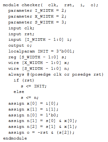
Fig 2. Verilog code implementing functionality of assertion assert {a ; b}
EXAMPLE 2
The second example is somewhat more complex:
assert never {{a;b[*]} : {c[*];d} ; e}Items b[*] i c[*] represent according to PSL syntax sequences of b and c, that may occur any number of times or may not occur.
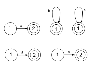
Fig.3 Graphs representing the following expressions: a, b[*], c[*], d, e
The atomic graphs are concatenated (as the respective items in the analyzed assertions are bound with concatenation operator). As the first step we generate graphs representing expressions in braces. The effect of concatenation of graphs a and b is shown in Fig. 3:
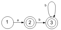
Fig 4. Result of concatenation of graphs a and b
The graph above could be further transformed to minimize the number of states. However, for the sake of clarity the authors do not want to deviate from the direct effects of concatenation of the algorithm as represented with respective pseudocode in [2]. After the fusion of graphs representing the clauses contained in the internal braces of the analyzed assertion we obtain the graph in Fig. 5. In the assertion syntax the combination of graphs by fusion algorithm is indicated by symbol ”:”.
The last item in the analyzed assertion is e and is preceded by the concatenation operator (;). Therefore the graph shown in Fig. 5 should be concatenated with the graph e (shown in Fig. 3). After taking into consideration the word never (we add the loop true in the state 1) we end up with the graph shown in Fig. 6.
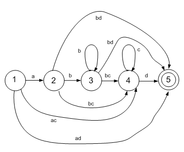
Fig 5. Fusion algorithm result
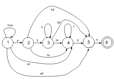
Fig.6 Final graph representingthe example PSL assertion
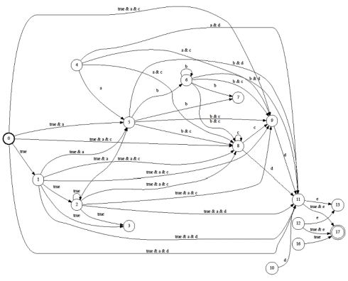
The graph in fig 6. should be obtained after optimization, but optimization algorithms have not been implemented yet by us. The graph generated from the assertion without any optimization is shown in fig. 7. It can be seen that dead states or unreachable states may occur during execution of the algorithms that derive the graph from assertion.
The graph can be implemented in hardware (as a Hardware Checker). The implementation of such circuit is straightforward. We assign a single D flip-flop to each state of the graph and the excitation function for that flip-flop is derived from logic expressions associated with the edges going into that state. It is then very easy to generate representation of such circuit in the hardware description language (Verilog in our example).
Fig. 7 Graph derived from the analyzed assertion with the MBAC algorithms [2]
Flip-flops are usually grouped into registers. The flip-flop on the most significant bit is representing the output of the assertion. Hardware Checker is synchronous and has synchronous reset. Verilog description of the Hardware Checker for the graph in fig. 7 is as follows.
module checker(
  clk,
  rst,
  i,
  o
);

  parameter I_WIDTH = 6;
  parameter X_WIDTH = 15;
  parameter S_WIDTH = 16;

  input clk;
  input rst;
  input [I_WIDTH - 1:0] i;
  output o;

  localparam INIT = 	6'b0000000000000001;

  reg [S_WIDTH - 1:0] s;

  wire [X_WIDTH - 1:0] x;
  wire [S_WIDTH - 1:0] n;

  always @(posedge clk or posedge rst)
    if (rst)
      s <= INIT;
    else
      s <= n;

  assign x[0] = i[0];
  assign x[1] = i[1];
  assign x[2] = i[2];
  assign x[3] = i[3];
  assign x[4] = i[4];


assign x[5] = i[1] & i[3];
assign x[6] = i[1] & i[4];
assign x[7] = i[2] & i[3];
assign x[8] = i[2] & i[4];
assign x[9] = i[5];
assign x[10] = i[0] & i[1];
assign x[11] = i[0] & i[1] & i[3];
assign x[12] = i[0] & i[1] & i[4];
assign x[13] = ~i[0];
assign x[14] = i[0] & i[5];
assign n[0] = 1'b0;
assign n[1] = s[0] & x[0];
assign n[2] = s[1] & x[0] | s[2] & x[0];
assign n[3] = s[1] & x[0] | s[2] & x[0];  assign n[4] = 1'b0;
assign n[5] = s[0] & x[10] | s[1]
	& x[10] | s[2] & x[10] | s[4] & x[1];
assign n[6] = s[5] & x[2] | s[6] & x[2];
assign n[7] = s[5] & x[2] | s[6] & x[2];
assign n[8] = s[0] & x[11] | s[1]
	& x[11] | s[2] & x[11] | s[4] & x[5]
	| s[5] & x[7] | s[6] & x[7] | s[8]  	& x[3];
assign n[9] = s[0] & x[11] | s[1]
	& x[11] | s[2] & x[11] | s[4] & x[5]
	| s[5] & x[7] | s[6] & x[7] | s[8]
	& x[3];
assign n[10] = 1'b0;
assign n[11] = s[0] & x[12] | s[1]
	& x[12] | s[2] & x[12] | s[4] & x[6]
	| s[5] & x[8] | s[6] & x[8] | s[8]
	& x[4]	| s[9] & x[4] | s[10] & x[4];
assign n[12] = 1'b0;
assign n[13] = s[11] & x[9] | s[12]
	& x[9];
assign n[14] = 1'b0;
assign n[15] = s[11] & x[14] | s[12] & 	x[14] | s[14] & x[0];
assign o = ~rst & (s[15]);

endmodule
In the Verilog code above the literal e from the analysed assertion is represented by i[5], d is represented by i[4], c by i[3], b by i[2], a by i[1] and 1'b1 is kept in i[0].
CONCLUSIONS
For some categories of functional blocks (IP cores) hardware assisted verification has to complement simulation in the process of functional verification due to excessive simulation times.
Interaction of the hardware prototype with original software testbench makes using the same test suits in simulation and hardware assisted verification easier.
Synthesizable assertions enable easier locations of errors discovered during hardware assisted verification.
Application of these approaches to the verification of JPEG 2000 encoder proved viability of these concepts and resulted in up 300x shorter test execution times in regression testing.
LITERATURE
[1] H. Foster, A. Krolnik, D.Lacey.: Assertion Based Design, Kluwer Academic Publishers, 2003
[2] M. Boule, Z. Zilic.: Generating Hardware Assertion Checkers, Springer Verlag, 2008
[3] User’s Manual. FoCs - Formal Checkers - a Productivity Tool, ver 1.0, IBM Research Lab in Haifa, April 2003
[4] A. Koczor, W. Sakowski, SystemC library supporting OVM compliant verification methodology, Proceedings of IP SoC 2011 Conference, Grenoble, France, December 2011
[5] I. Sobanski, W. Sakowski, Verification of USB 3.0 Device IP Core in Multi-Layer SystemC in Proceedings of IP-ESC 2009 Conference, Grenoble, France, 1-2 December 2009
[6] Standard Co-Emulation Modeling Interface, Release 2.1, Acellera, 2011
[7] Property Specification Language Reference Manual, version 1.1, Accellera, 2004
Related Semiconductor IP
- NPU IP Core for Mobile
- NPU IP Core for Edge
- Specialized Video Processing NPU IP
- HYPERBUS™ Memory Controller
- AV1 Video Encoder IP
Related White Papers
- Is Agile coming to Hardware Development?
- Verification of various SoC features through SV assertions
- Floating-point FFT with Minimal Hardware
- Applying Continuous Integration to Hardware Design and Verification
Latest White Papers
- Ramping Up Open-Source RISC-V Cores: Assessing the Energy Efficiency of Superscalar, Out-of-Order Execution
- Transition Fixes in 3nm Multi-Voltage SoC Design
- CXL Topology-Aware and Expander-Driven Prefetching: Unlocking SSD Performance
- Breaking the Memory Bandwidth Boundary. GDDR7 IP Design Challenges & Solutions
- Automating NoC Design to Tackle Rising SoC Complexity
