Simplifying DSP Hardware Development within a MATLAB-based Design Flow
Historically, exploiting FPGA or ASIC implementation of DSP algorithms has been the domain of companies with highly-skilled designers and large budgets. Now, a new generation of tools is bringing hardware-based DSP implementation within the reach of a much wider community through a new paradigm in DSP design: algorithmic synthesis. Eric Cigan, AccelChip, Inc. and Aaik van der Poel, Synopsys, cover the design flow issues in detail in this two-part article.
Part 1: From Algorithm to Architecture Specification
The increasing performance requirements of the latest defense, communications and consumer products demand a shift from software to hardware implementation, especially for the compute-intensive Digital Signal Processing (DSP) algorithms. To take advantage of the improved performance that hardware implementation offers requires more automation and collaboration between the system level specification and implementation.
The ability of algorithm developers, system engineers and hardware designers to collaborate effectively on a project partly depends on having available a true top-down DSP design methodology. Algorithmic synthesis tools can support this approach, but must provide an effective link with the tool environments that are commonly used to specify and explore at the algorithmic level. A primary requirement is to be able to automatically evaluate potential implementation options during early design stages, and rapidly make design tradeoffs. This ability will provide the foundation for a low-risk methodology that produces the most cost-effective designs, while still meeting design specifications.
DSP Implementation Alternatives
Designers have available to them a variety of implementation options for DSP algorithms, each of which is suited to different classes of problems.
- Application-Specific Integrated Circuit (ASIC) – Customized chips of digital logic designed from standard cells.
- Application-specific standard product (ASSP) – Dedicated chip sets, e.g., MPEG-4 decoders.
- Field Programmable Gate Array (FPGA) – Arrays of gates that can be reprogrammed though downloading a bitstream – primarily from Xilinx and Altera.
- General-purpose processor (GPP) – software programmable devices, such a those from Intel, Freescale, ARM, MIPS.
- DSP – software programmable device optimized for numerically-intensive tasks – primarily from TI, Analog Devices and Freescale.
The implementation technology that is right for a particular project depends on many factors. In general, the hardware implementations (ASIC, ASSP and FPGA) enjoy performance advantages over software implementations (GPP and DSP), while software implementations have provided much easier and less expensive development environments. Performance-critical functions can also be migrated from software to silicon by using a hybrid approach: GPPs and DSPs can be augmented with “hardware accelerators” implemented in FPGAs/ASICs. Figure 1 shows how TI achieved a 16-times performance boost through use of a Viterbi coprocessor for its C6000 family of DSPs [1].
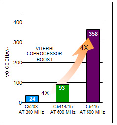
Figure 1: Example of hardware accelerator: Viterbi coprocessor in TI TMS320C6000 platform (source: TI)
Conventional DSP hardware design flows
Figure 2 shows a general form of a typical DSP hardware design flow. DSP design has traditionally been divided into two types of activities – systems/algorithm development and hardware/software implementation. These tasks have been accomplished by two very disparate groups of engineers that often have little connection or interaction.
The flow originates with algorithm developers and system engineers. Algorithm developers create, analyze and refine the required DSP algorithms using mathematical analysis tools at the behavioral level, often without consideration for the underlying system architecture or hardware/software implementation details. The system designer is concerned with defining the functionality and architecture of the design to adhere to the product specification and interface standards. Systems designers and algorithm developers interact efficiently with each other because they work in a common design environment based on a high-level programming language. According to market research firm Forward Concepts as well as reports in FPGA and Programmable Logic Journal, the majority of DSP system designers and algorithm developers use the MATLAB® language from The MathWorks®. [2]
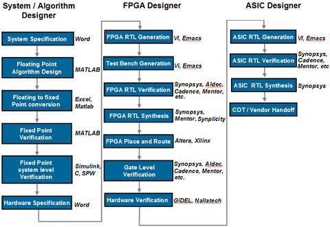
Figure 2: Conventional DSP hardware design flow
In contrast, hardware designers take the specifications created by the systems engineers and algorithm developers and are tasked to create a physical implementation of the DSP design. If the target of the DSP algorithm is an FPGA, structured ASIC, ASIC or SOC, the first task is to create a register transfer level (RTL) model in a hardware description language (HDL) such as Verilog or VHDL. The hardware designer must have a sufficient understanding of communications theory and signal processing to be able to interpret the written specification provided by the systems engineer. The process of creating an RTL model and a simulation testbench usually takes many months because of the need to verify that the manually created RTL file exactly matches the MATLAB model.
Once the RTL model and simulation environment is created, the hardware designer interacts with the systems engineers and algorithm developers to analyze the performance, area and functionality of the hardware realization of the DSP system. It is quite common for the original algorithms and system architecture to be modified because the systems engineers had no visibility into the physical design domain during the algorithm development. The iteration process continues – refine the algorithms and system architecture, update the written specification, modify the RTL models and testbenches, and resimulate – until the DSP system requirements are met by the hardware realization. The design flow then continues with a standard FPGA and/or ASIC top-down design flow using logic synthesis, and ultimately physical design tools to place and route the netlist in a given FPGA or ASIC device.
Efficient DSP Design Creation with MATLAB
In the DSP domain, MATLAB® is the design language of choice, providing an efficient system-level verification environment, a variety of design tools, and advanced graphical tools for 2D, 3D and animated visualization. Built-in abstractions liberate the designer from the strict modeling style guides that are required by general-purpose languages, allowing large design objects to be represented with a high degree of efficiency.
To demonstrate MATLAB’s efficiency in modeling and analyzing a DSP algorithm, it is useful to consider a detailed example.
MATLAB Model for 3-Dimensional Vector Rotation Consider an algorithm that implements a rotation of a three-dimensional vector by rotations á, â, and ã around the x, y and z axes, respectively, as shown in Figure 3. [3]
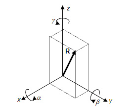
Figure 3: 3-Dimensional Vector Rotation
This vector rotation could be computed as a series of successive coordinate transformations in the form of matrix multiplications. The matrix equation takes the following form:
Rrot = Tã · Tâ · Tè · R
where R is the original vector in a three-dimensional coordinate system, Tè, Tâ and Tã are 3-by-3 matrices and Rrot is position of the original vector after applying three rotations.
Algorithm developers like to use the MATLAB language to develop this sort of algorithm for several reasons. First, variables in MATLAB can be of many types including scalars, vectors and matrices, so the algorithm developer doesn’t have to declare variables or create iterative loops to implement operations on these types. Second, the MATLAB language has a wealth of built-in mathematical functions that let the designer focus on the top-level algorithm rather than re-implementing – in this case trigonometric operations such as sine or cosine. Third, MATLAB allows hierarchical design so that complex functions can be structured in a form that is natural to the developer and easy for other members of a design team to understand. Finally, the MATLAB environment has a wide array of visualization tools that span 2-dimensional and 3-dimensional plotting, as well as animated graphics.
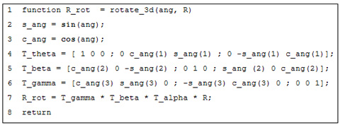
Figure 4: MATLAB algorithm implementing 3-D vector rotation
For the coordinate rotation example, MATLAB allows this algorithm to be written concisely as shown in Figure 4. In this MATLAB M-file, ang is a 3-vector of the rotation angles {á, â, ã}, R is a 3-vector representing the Cartesian coordinates of the vector R, and R_rot is a 3-vector representing the Cartesian coordinates of the rotated vector Rrot. What’s significant is that a single line of MATLAB code, such as line 7, expresses the product of three matrices and a vector. In other high-level languages such as C, this would need to be broken up into the different matrix products with the use of nested loops to index through the matrices and compute the inner products. This compact format makes the design easier for the algorithm developer because it preserves the structure and intent of the algorithm.
This algorithm can be readily embedded within a script file that creates stimulus and displays results; Figure 5(a) shows is an example of such a script file with the corresponding results shown in Figure 5(b).
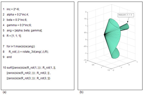
Figure 5: 3-D Vector Rotation design. (a) Script M-file for design in MATLAB. (b) Simulation results for results using this script file.
Converting Floating-Point to Fixed-Point
The mathematically-intensive nature of DSP algorithms raises the issues of precision and computation accuracy. DSP algorithm developers often begin work in floating point arithmetic because it provides the most generality in evaluating the benefits of candidate algorithms. However, when it comes to implementing an algorithm in hardware, there are benefits and trade-offs to using fixed-point hardware rather than floating-point hardware. DSP applications such as handheld devices or aerospace systems require low-power and cost-effective circuitry; fixed-point hardware tends to be simpler and smaller, these units require less power and cost less to produce than floating-point circuitry.
The difficulty with fixed-point implementations is that they are more complex to design. Floating-point numbers use a scaled number multiplied by an exponent to represent a broad dynamic range while maintaining significant precision. Fixed-point numbers lack the exponent, so the number of bits must be carefully chosen to constrain the impact of overflows and underflows while minimizing the bit-width of numbers.
Algorithmic Synthesis – A Brief Review
Algorithms start life as descriptions that are very functional in nature. These functional descriptions often lack specific digital implementation details like bit precision, timing and micro-architecture. In fact, hardware designers refer to them as descriptions at the un-clocked, or algorithmic level. The predominant hardware implementation technique, RTL design, does require the introduction of timing and forces us to make a choice in micro-architecture. This choice is often based on already available and completed design parts (strategy of risk avoidance) or pure empirical knowledge (strategy of experience) and might not be the most optimum choice.
As illustrated in Figure 6, algorithmic synthesis bridges this void by automating the process of creating the micro-architecture based on constraints like overall latency, throughput, cost (silicon area) and performance (clock speed). It also opens the door to exploring multiple architectures quickly before committing to a particular implementation.
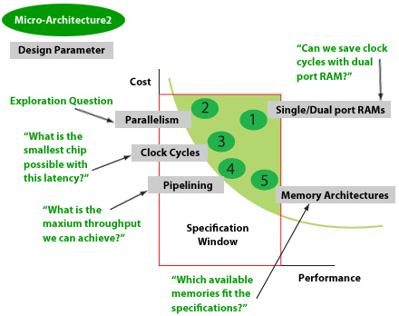
Figure 6: Algorithm Synthesis allows for quick exploration of multiple implementation options from a single source
Summary and Next Steps
In the first part of this article, we have seen that what used to be a field of expertise founded on "exclusive knowledge” is slowly but surely being drawn into mainstream design because of the demanding signal processing functions in today's imaging, consumer and mil/aero applications.
The time-consuming nature of the traditional design flow, with a manual gap between algorithm development and implementation, is no longer acceptable. In this first part we have touched on why the algorithm developers prefer to use the MATLAB language and analysis environment, and why it is worlds apart from what hardware designers like to see as a starting point.
In the next section we will take a peek under the hood of what algorithm synthesis actually does when it automatically converts the fixed point MATLAB functional descriptions to Register Transfer Level hardware descriptions, thus closing the "exclusive knowledge" bridge with an automated, repeatable and risk reducing flow step. We will also highlight how we further can decrease our risk of misinterpretations when we move from prototyping in FPGAs to production in ASICs.
References
[1] Leon Adams, Texas Instruments, “Semiconductor options for real-time signal processing,” EDN, November 25, 2004, p. 87-94.
[2] Kevin Morris, “Destination DSP: Methodologies for Signal Processing Success,” FPGA and Programmable Logic Journal, Volume 5, Number 9, November 30, 2004.
[3] Eric W. Weisstein. “Rotation Matrix.” From MathWorld – A Wolfram Web Resource. http://mathworld.wolfram.com/RotationMatrix.html
 Eric Cigan
Product Marketing Manager, AccelChip Inc.
As product marketing manager for AccelChip Inc., Eric Cigan is responsible for product planning and promotion for the AccelChip product family. He has more than fifteen years' experience in the EDA industry.
He was most recently at Mentor Graphics, Inc., where he managed product marketing and business development in Mentor's hardware/software co-verification business. Prior to this, Cigan held positions as aerospace/automotive segment manager for Analogy (now part of Synopsys) and product marketing manager, account manager and research engineer at Integrated Systems, Inc. (now part of Wind River).
Cigan began his career in control system design at the Lockheed Missiles & Space Company and the Charles Stark Draper Laboratory. Cigan holds S.B. and S.M. degrees in Mechanical Engineering from the Massachusetts Institute of Technology.
 Ir. Aaik van der Poel
Group Marketing Manager, Synthesis, Synopsys
Aaik van der Poel currently oversees various aspects of the Synopsys (structured) ASIC, Behavioral, C-based, and FPGA synthesis product lines, and has over 20 years EDA marketing, sales and support experience.
He joined Synopsys in 2000 and was responsible for the CoCentric SystemC synthesis product line introduction. Prior to joining Synopsys he held senior marketing and application positions at Mentor Graphics and Tektronix Europe and was a chip designer at ICN design house in the Netherlands. Van der Poel holds a M.S. in Electrical Engineering from the University of Twente in the Netherlands and a patent on isochronous (large) system design.
WEB LINKS
- AccelChip
- Synopsys Synthesis Solutions
- MATLAB
![]()
TRADEMARK NOTICE
AccelChip and AccelWare are registered trademarks of AccelChip Inc. Design Compiler, DesignWare, Formality, Synopsys , VCS and the Synopsys logo are registered trademarks of Synopsys, Inc., and Galaxy is a trademark of Synopsys, Inc. MATLAB is a trademark of The MathWorks, Inc. All other trademarks or registered trademarks mentioned in this document are the intellectual property of their respective owners.
©2005 Synopsys, Inc. Synopsys and the Synopsys logo are registered trademarks of Synopsys, Inc. All other company and product names mentioned herein may be trademarks or registered trademarks of their respective owners and should be treated as such.
Related Semiconductor IP
- Wi-Fi 7(be) RF Transceiver IP in TSMC 22nm
- PUF FPGA-Xilinx Premium with key wrap
- ASIL-B Ready PUF Hardware Premium with key wrap and certification support
- ASIL-B Ready PUF Hardware Base
- PUF Software Premium with key wrap and certification support
Related White Papers
- HW/SW Interface Generation Flow Based on Abstract Models of System Applications and Hardware Architectures
- VLSI Physical Design Methodology for ASIC Development with a Flavor of IP Hardening
- Four ways to build a CAD flow: In-house design to custom-EDA tool
- A Survey on the Design, Detection, and Prevention of Pre-Silicon Hardware Trojans
Latest White Papers
- Boosting RISC-V SoC performance for AI and ML applications
- e-GPU: An Open-Source and Configurable RISC-V Graphic Processing Unit for TinyAI Applications
- How to design secure SoCs, Part II: Key Management
- Seven Key Advantages of Implementing eFPGA with Soft IP vs. Hard IP
- Hardware vs. Software Implementation of Warp-Level Features in Vortex RISC-V GPU