Challenges and Benefits of Low Power Design Verification with CPF for a standalone IP
Shalini Damani, Sunny Aggarwal (Freescale)
Abstract :
With the declining gate length in new process technologies, static power dissipation becomes a bigger problem. Nowadays, power is replacing performance as the key competitive metrics in SoC. This triggers the need for multi-voltage management techniques.CPF or Common Power Format provides techniques and concepts that can be applied at various stages throughout low-power SoC design development to express the power intent of an IC design.
PROBLEM STATEMENT
Though CPF has been used aggressively at SoC level power simulations, its use at IP level has always been minimal. This paper exploits the use of CPF for IP level power simulations and also importance of CPF for IP level. This paper analyses the challenges and benefits of using CPF in low power design verification at IP level.
BASIC TERMS & RULES OF CPF USED
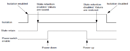
Basic Transition sequence:

Figure 1
In the figure 1, power down and power up will be referred to as shutoff condition in this paper. State retain is not dealt with in this paper.
CHALLENGES
- Availability of CPF file:
Generally, cpf file is available for the SoC level but for the standalone IP level testbench, this file needs to be written or modified from present SoC file.
Understanding various power modes from IP perspective:
Many power modes which are applicable at SoC level might not be of value for IP level simulations. For example, at SoC level there can be numerous power modes as shown in the code snippet below:
create_power_mode -name RUN
-domain_conditions {
....
} -default
create_power_mode -name VLLS3
-domain_conditions { .... }
create_power_mode -name VLLS2
-domain_conditions { .... }
create_power_mode -name VLLS0_1
-domain_conditions { .... }
But at IP level only two of these four modes might be of use, for example:
create_power_mode -name MODE_ALL_ON
-domain_conditions { ....
}-default
create_power_mode -name MODE_SW_OFF
-domain_conditions { .... }
Here, RUN at SoC corresponds to MODE_ALL_ON at IP.
Difference in the power down/up sequence:
There might be differences in the power up/down sequence used at IP and SoC which will result in propagation of an unknown state if not understood properly. In fact, the design can have isolation cells which are different at SoC and IP.
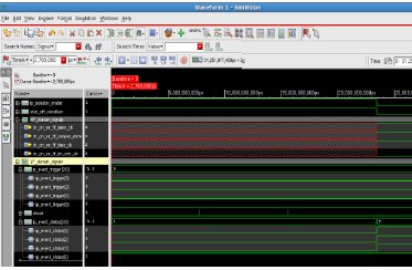
Following is the snapshot of a problem that can occur due to incorrect isolation enable and shutoff condition:

Figure 2
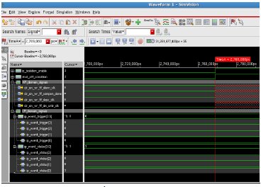
Below figure shows violation of CPF rules mentioned in figure 1 in the implementation above:

Figure 3
In figure 2, there is propagation of an unknown state leading to incorrect status (ip_event_status) getting set as there is no corresponding ip_event_trigger. In this example, the isolation enabling and shutoff condition defined were such that negation of shutoff condition led to isolation being enabled. This IP when integrated with SoC uses different isolation cells and the problem was not apparent. So, with the assertions in IES being enabled the difference in two implementation was clear. This problem when fixed led to following snapshot, without any unknown state propagation:

Figure 4
As it can be seen from figure 4, there is no unknown state propagation anymore. Also, another observation is clkout comes correctly which was missing in figure 2 after shutoff condition was removed.
- Separating boundary ports at IP level
Boundary ports may differ from SoC as CPF is now made at a micro level.
- Shutoff condition and isolation enable needs to be carefully specified in the design.
The above conditions should correctly follow the power up/down sequence.
BENEFITS
- The above observations show that power simulations are necessary for low-power IPs with different power domains
- Isolation rules can be robustly checked and removes human errors
- When implemented at an early stage any false isolation can be corrected.
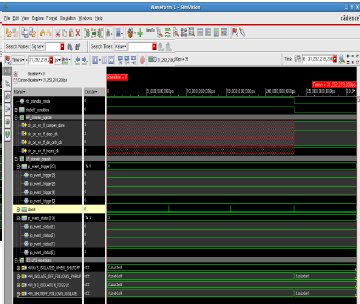
- Cadence Simvision, with its CPF inbuilt assertions, helps in putting basic checks to ensure that CPF rules are followed. As can be seen from figure 5 below, if rules in figure 1 are not followed properly following assertions fail:

Figure 5
- Assertions make sure that power-up/down is correct even at standalone IP level.
- Knowledge of Power-up/down sequence becomes clear
- All mode transitions can be checked effectively.
- Helps in understanding the difference between SoC and IP level isolation rules
REFERENCES
1. Low Power Design using the Si2 Common Power Format by
Susan Carver, Si2 Anmol Mathur,Calypto Design Systems
Lalit Sharma, Apache Design Inc.
Prasad Subbarao, LSI Corporation
Steve Urish, IBM Corporation Qi Wang, Cadence Design Systems
2. Power Management in SoC using CPF by
Lakshmi M S, Dept. of ECE. Amrita School of Engineering
Bengaluru, India
Email: lakshu.ms@gmail.com
Pukhraj Vaya, Dept. of ECE, Amrita School of Engineering
Bengaluru, India
Email: prvaya@gamil.com
Srinivasan Venkataramanan, CVC Pvt. Ltd.
Bengaluru, India
Email: srini@cvcblr.com
3. Cadence Low-power Simulation Guide (version 12.1)
Related Semiconductor IP
- NPU IP Core for Mobile
- NPU IP Core for Edge
- Specialized Video Processing NPU IP
- HYPERBUS™ Memory Controller
- AV1 Video Encoder IP
Related White Papers
- Low Power Analysis and Verification of Super Speed Inter-Chip (SSIC) IP
- Context Based Clock Gating Technique For Low Power Designs of IoT Applications - A DesignWare IP Case Study
- VLSI Physical Design Methodology for ASIC Development with a Flavor of IP Hardening
- Low Power Design in SoC Using Arm IP
Latest White Papers
- Transition Fixes in 3nm Multi-Voltage SoC Design
- CXL Topology-Aware and Expander-Driven Prefetching: Unlocking SSD Performance
- Breaking the Memory Bandwidth Boundary. GDDR7 IP Design Challenges & Solutions
- Automating NoC Design to Tackle Rising SoC Complexity
- Memory Prefetching Evaluation of Scientific Applications on a Modern HPC Arm-Based Processor
