A SystemVerilog DPI Framework for Reusable Transaction Level Testing, Debug and Analysis of SoC Designs
San Jose, CA, USA
ABSTRACT
Complex system design requires modeling, testing, debug and analysis of many levels of abstraction with varying levels of accuracy. Reuse from previous steps is important at each step of the design verification and each step of the modeling. This paper describes a transaction based framework for reusing tests and modeling based on inter-language function calls (ILFC) using SystemVerilog DPI (Direct Programming Interface) [1] and C.
1. INTRODUCTION
SystemVerilog and SystemVerilog DPI along with ANSI-C can be used to create a reusable framework for verification. C is used to write tests, with hardware models in either C or SystemVerilog depending on modeling accuracy requirements. SystemVerilog DPI is used to connect the C tests and the SystemVerilog models.
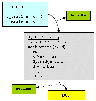
Figure 1: C tests calling SystemVerilog functions
C is a powerful language to describe functional behavior, but lacks native parallelization and lacks a way to model time. Using SystemVerilog DPI, the native threading and the event and time constructs of SystemVerilog can be accessed as needed from C – allowing the best of C – natural functional description, with the best of SystemVerilog – natural parallelization, time and events.

Figure 2: C tests calling C functions (no timing)
2. MODELING
The decision to use C or SystemVerilog to model a component of a system is largely dependent on the detailed timing accuracy required in the model. As design and verification proceeds, continuous refinement will guarantee that mixed language and mixed accuracy models will always be present [11]. It will be important to allow models with varying timing abstractions – such as OSCI PV, PVT, CA and high level un-timed models to operate together.
C models are written for the high level tests, and modeling is done in C unless there are detailed timing issues better modeled in SystemVerilog. C models have the advantage of being portable and commonly used for functional description, easy to debug, and easy to run. SystemVerilog models are used to model lower level details and timing or event synchronization issues for which C is not well suited. SystemVerilog DPI is used to connect the C and the SystemVerilog models.
2.1 Modeling transactions
In SystemC [5] SCV concepts of streams, transactions, attributes and relations are introduced. These concepts are useful to model transactions. [9] provides additional modeling concepts and ideas.
Streams are collections of transactions that are modeled together for some purpose – for debug – for analysis – for graphical display. Sometimes streams are used to represent a thread of control – like a finite state machine. These modeling decisions are very application and methodology specific.
A transaction is a communication between two objects. The communication has a begin time, and end time, and a variety of attributes. The attributes are custom – there can be many kinds of transactions with many kinds of attributes.
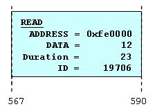
Figure 3: A transaction with attributes

Figure 4: Two streams with transactions
Transactions can have relationships with other transactions. A relationship is a 3-tuple (rName, tr1, tr2), where rName is the relation name, and tr1 and tr2 are the two transactions involved in the relationship. Relationships can be a directional relationship between two transactions like “tr1 is a predecessor to tr2” (“pred”, tr1, tr2), “tr4 is a child of tr5” (“child”, tr4, tr5). Relationships can also be collections of transactions that share the same tag or property – “all the BLUE transactions” or “all transactions with id=34”.
2.2 Parallelism, timing and events
Since C has no built-in timing, event handling or multi-threading, when using SystemVerilog DPI with C, timing, events and threading should be modeled in the SystemVerilog simulation kernel. By calling SystemVerilog DPI exported tasks, C can wait for an event, or can wait for N time units. Additionally, using SystemVerilog fork/join, the imported SystemVerilog DPI C function calls can easily become multi-threaded.
A SystemVerilog DPI imported C task c_task1() that has become multi-threaded:
c_task1(…);
c_task1(…);
join
A C-callable SystemVerilog DPI exported task that will wait for N clocks.
while(n-- > 0)
@posedge clk;
endtask
A C-callable SystemVerilog DPI exported task that will wait for 10 time units.
#10;
endtask
C code using the SystemVerilog DPI exported timing and synchronization entry points that writes to an address, waits for 3 clocks, then waits for 10 time units and writes to another address:
write_mem(addr, wdata1);
wait_nclks(3);
wait_10();
write_mem(addr+4, wdata1);
}
These are some simple examples of C calling SystemVerilog and using SystemVerilog to thread C code. More sophisticated models and techniques are possible using the full range of the SystemVerilog DPI interface and other SystemVerilog features.

Figure 5 : Recording transactions from C, SV
3. TRANSACTION RECORDING
Traditional transaction based debugging and analysis assumes that collections of transactions are available – usually as a recorded database. The SystemC SCV recording specification is available for SystemC users, but SystemVerilog and C models have no standardized way to collect transactions. In order to create a recorded database from SystemVerilog and C, we need an API in common, as in Figure 5. The proposed PLI based Draft Standard for Verilog Transaction Recording [7] is a good start, but must be augmented with a C implementation, enhanced and extended to support other important constructs like tags and enhanced to provide transaction analysis capabilities from both a static recorded database and live simulation.
3.1 Transaction recording interface
Transactions can be thought of as function calls – there is a start and end of a transaction – as a function call begins and ends. A transaction has attributes with values – a function has arguments with values. SystemVerilog tasks and functions and C functions can be thought of as transactions. Table 1 shows function calls mapping to “transactions”.
A transaction recording interface can be built which is callable from C, from SystemVerilog via a PLI layer or from SystemVerilog via a DPI-C call (Figure 6).
Table 1: C and SystemVerilog calls mapping to Transactions
| Functions | Transaction Definition |
| A C function definition: c_task(int a…) A C function call: c_task(4); | Type = “c_task” Attr a = 4 |
| A SystemVerilog exported task definition: task sv_task( input int b…)
sv_task(5); | Type = “c_task” Attr b = 5 |
Using this transaction recording interface, (Figure 5) a test starts in C, a transaction is recorded, and as the test is decomposed by the test infrastructure into lower level calls – either C or SystemVerilog, each lower level transaction is recorded – using any of the available interfaces (C or SystemVerilog PLI or SystemVerilog DPI).
When writing tests and modeling in C, the function calls can be captured as transactions using the C transaction recording interface. When the C tests call SystemVerilog DPI tasks and functions via the DPI layer, the same C based interface can capture transactions. Each C function call, inter-language function call or annotated SystemVerilog task or function call is a transaction that is recorded.
The DPI or PLI transaction recording interface is used in the same way as the C interface – but it is used within a SystemVerilog model. Each task or function call in SystemVerilog can be recorded using the PLI or DPI.
3.2 Requirements for an API
The transaction recording API must support recording all transaction modeling constructs, including streams, overlapping transactions, non-overlapping transactions, begin/end times, transactions that occur in the past, relations between transactions, etc. Attributes can be added to a transaction anytime between the begin and end time. Attributes can have many types including char, short, int, long, long long, float, double, structs, arrays, unions and combinations of these.
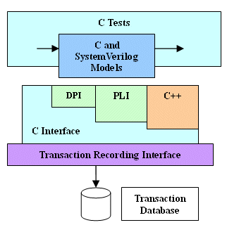
Figure 6 Transaction Recording APIs
The transaction database may contain transactions from the tests and from the C and SystemVerilog models – allowing detailed analysis and debugging. These recorded transactions are interchangeable, and have no limitations based on which interface was used to record them, (Figure 6).
4. TRANSACTION ANALYSIS
4.1 Comparison
As designs are refined, comparison of results can be used to verify matching behavior. Transactions modeled at different abstraction levels – behavioral, RTL, gate or PV, PVT, cycle accurate can generate an ordered collection of transactions which can be compared between levels. Exact timing matches in transaction comparison is unlikely, since the timing between modeling abstraction levels and the timing between architectural modeling levels is guaranteed to be different.
For most refinements the original design and the refined design will behave differently – since arbitration may change, timing is more detailed, etc. Despite the natural differences in refined versions, there are common behaviors which can be matched. For example, an image processing algorithm will still produce an image – but the order of pixel generation may be different, or slight differences in pixel values may occur. Differences that we want to find might be pixel values that are grossly incorrect, or image creation that takes 2x more cycles.
Exact matches are easy – they match. More difficult are streams of transactions with differences –sometimes a stream with differences should match. The acceptable differences can be re-ordered transactions, delayed transactions, repeated transactions, or transactions with missing attributes.
Usually transaction comparisons with missing attributes, out-of-order transactions, dropped transactions and repeated transactions will be treated as matches.
Waveform comparison is familiar to many people - and can be used to compare data from designs with different timing details; for example simple gate timing, back-annotated interconnect timing, RTL timing estimates. Timing simulation and cycle accurate unit-delay simulation can be compared at cycle boundaries – the timing approximations guarantee that the timing at cycle boundaries should match.
Similar kinds of approximations can be made for comparing transactions. In the case of transactions the application under consideration can help direct how transactions can be matched. For example, an image processing application could compare various levels of transaction details – compare at the “entire image”, compare at a “drawn horizontal line”, compare at a “drawn quadrant”, compare at a “drawn pixel”, etc. Comparing at “drawn pixel” may be a bad place to compare, since architectural changes like parallel memory access or pipelined computes may affect the pixel drawing order.
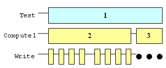
Figure 7: Simple write interface – no burst
4.1.1 Simple example
An example comparison of three different memory architectures will illustrate comparing transactions – a simple single write (Figure 7), burst write with no parallel operations (Figure 8), and burst write with two outstanding write operations in parallel (Figure 9).

Figure 8: Non-overlapping write transactions
The boxes labeled ‘1’ can be matched. The boxes labeled ‘2’ can be matched, etc. This application cannot compare the “burst” transactions, since one of the refinements has no burst behavior.
The writes cannot be compared as easily, since they are not strictly ordered.
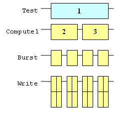
Figure 9: Overlapping write transactions
4.1.2 Timing considerations
Functional models are created and refined with additional timing details as needed to correctly model and analyze behavior and performance.
These timing additions enable more accurate system analysis, but can cause difficulties in various ways. Timing accuracy is a trade-off. If there is no timing – or limited timing, functionality may be modeled correctly, but timing and ordering may not be modeled exactly. If there is very detailed exact timing, simulation will be prohibitively slow.
Timing accuracy is important to model all conditions in a system, but usually implies interoperating with a timing wheel, or event management system, which implies context switches, and other operations that will affect overall model speed. Additionally, these timing changes may cause subtle changes in the transaction behavior.
In order to avoid problems with simulation speed, various approximations are used to improve performance without affecting functionality and timing accuracy.
4.2 Performance Analysis
Attributes, relationships and tags can be used to allow run-time or post-processing of transactions to measure performance. Attributes can be annotated to the transactions either during simulation or as part of a post-processing step. Relationships and tags are used to collect transactions together.
Collections of transactions that are related can be processed as a group, for example, all transactions that are WRITE with address range N < addr < M can have their duration attribute summed. In general an arbitrary collection of transactions, related by tag, relation or attribute can be processed. Example processing is summing properties, averaging, min/max etc.
As modeling abstractions change, performance measures change as well. For high level models, throughput and overall bandwidth may be the most important performance measures. For lower level models, additional measures may become important – like retry counts, idle cycles, and other bus timing issues. Targeted applications will also affect performance analysis criteria. Image applications may only be concerned about “painting all the correct pixels within a frame time unit” (the order is not important), whereas a network application may be concerned about making sure the packet order is correct. The differences in criteria are important for both performance measurement and comparison.
A form of performance analysis can be used as part of the comparison. For example, the bytes/second through an interface should be relatively the same as the model is refined. If the throughput changes dramatically, modeling errors or timing problems may have occurred.
5. CONCLUSION
Figure 10 is the goal. Transaction recording and analysis performed against SoC designs modeled at various levels of abstraction or with various underlying architectures all using common APIs.
SystemVerilog DPI and C can be used to model large SOC designs, and can be annotated to record transactions from a variety of timing and modeling accuracy levels using a common interface. These levels can be used for effective verification and performance analysis.

Figure 10: Post-processing and live analysis
A transaction recording API must be standardized for use with SystemVerilog and C. SystemC SCV and proposed Verilog PLI [7] standards must be extended and enhanced.
6. FUTURE WORK
6.1 Transactions
In SystemVerilog, a task or function can be used as a “transactor” – for example a read function call
output bit[4:0]data)
might have lower-level signals associated with it that actually do the lower level signaling – like RW, ENABLE and ACK signals. These associated signals can be annotated in the transaction as a part of the transactions – they are the low level implementation of the read_mem() call.
6.2 Automated recording
Structural elements within SystemVerilog can have their arguments automatically recorded – this simple addition allows transactions to be added to existing code with little or no change to the source code. For example, a global setting could be applied to a design that turns on automatic task transaction recording. Or each task can be annotated with a “transaction pragma”. Each such marked task in the design will be annotated with recording interfaces, and each time the task executes a transaction will be recorded along with any parameter values.
6.3 Other modeling and language constructs
Interfaces and modports are other places that automated transaction recording can be used. Additional automated annotation at other design constructs is possible – any place where information is transferred – any place data is communicated between objects is a likely candidate for recording information as a transaction.
7. REFERENCES
[1] SystemVerilog LRM, www.systemverilog.org
[2] Bart Vanthournout, et al. Developing Transaction-level Models in SystemC, www.us.design-reuse.com/articles/article8523.html
[3] Deneault, et al., Retargetable Transaction-Based System Level Verification, www.aptix.com/literature/whitepapers/Transactions_White_Paper.pdf
[4] Open Core Protocol (OCP) Specification 2.1 , www.ocpip.org
[5] OSCI TLM Standard, www.systemc.org
[6] Tim Kogel, et al., CoWare, OCP TLM for Architectural Modeling
[7] Draft Standard for Verilog Transaction Recording, www.boyd.com/1364_btf/report/full_pr/attach/435_IEEE_TR_Proposal_04.pdf
[8] Sudeep Pasricha, Nikil Dutt, Mohamed Ben-Romdhane, Extending the Transaction Level Modeling Approach for Fast Communication Architecture Exploration. DAC 2004.
[9] Mark Glasser, The Transaction Data Model, unpublished work. October 2005.
[10] Alain Clouard, Kshitz Jain, et. al., Using transactional level models in a SoC design flow, SystemC: methodologies and applications, pp. 29-63, Kluwer 2003, ISBN: 1-4020-7479-4
[11] Lukai Cai and Daniel Gajski, Transaction Level Modeling: An Overview, CODES + ISSS’03, October 1–3, 2003
[12] Frank Ghenassia (Ed.), Transaction-Level Modeling with SystemC, Oct 2005, ISBN: 10 0-387-26232-6.
Related Semiconductor IP
- HBM4 PHY IP
- Ultra-Low-Power LPDDR3/LPDDR2/DDR3L Combo Subsystem
- HBM4 Controller IP
- IPSEC AES-256-GCM (Standalone IPsec)
- Parameterizable compact BCH codec
Related Articles
- Design and Implementation of Test Infrastructure for Higher Parallel Wafer Level Testing of System-on-Chip
- A RISC-V Multicore and GPU SoC Platform with a Qualifiable Software Stack for Safety Critical Systems
- Design and implementation of a hardened cryptographic coprocessor for a RISC-V 128-bit core
- A new era of chip-level DRC debug: Fast, scalable and AI-driven
Latest Articles
- Pipeline Stage Resolved Timing Characterization of FPGA and ASIC Implementations of a RISC V Processor
- Lyra: A Hardware-Accelerated RISC-V Verification Framework with Generative Model-Based Processor Fuzzing
- Leveraging FPGAs for Homomorphic Matrix-Vector Multiplication in Oblivious Message Retrieval
- Extending and Accelerating Inner Product Masking with Fault Detection via Instruction Set Extension
- ioPUF+: A PUF Based on I/O Pull-Up/Down Resistors for Secret Key Generation in IoT Nodes