MIPI IP
Filter
Compare
764
IP
from
57
vendors
(1
-
10)
-
MIPI D-PHY and FPD-Link (LVDS) Combinational Transmitter for TSMC 22nm ULP
- Technology is TSMC 22nm ULP 1p10M.
- Supply voltage can be applied 1.0V for core voltage, 1.8V for IO voltage.
- Maximum data rate of each channel is 1.5Gbps at High-speed mode for MIPI D-PHY Transmitter.
- Data rate of each channel is 609Mbps for FPD-Link(LVDS).
-
MIPI SoundWire I3S Manager IP
- The MIPI SoundWire I3S Manager IP enables efficient, low-power, and high-fidelity audio data transfer for mobile, consumer, and automotive applications.
- Compliant with the MIPI SoundWire I3S (Inter-IC Sound) standards, it supports synchronized, multi-channel audio over a scalable two-wire interface, ideal for connecting digital microphones, amplifiers, and codecs in space-constrained designs.

-
MIPI SoundWire I3S Peripheral IP
- The MIPI SoundWire I3S Peripheral IP delivers seamless, low-power, and high-quality audio connectivity for a range of mobile, consumer, and automotive devices.
- Fully compliant with the MIPI SoundWire I3S (Inter-IC Sound) specifications, it enables synchronized, multi-channel audio communication with a compact and efficient two-wire interface, ideal for integrating digital microphones, amplifiers, or audio codecs.

-
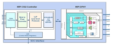
MIPI CSI2 Interface Solution
- Brite provides full solution for the MIPI CSI interface, which receives the data from sensors in PHY layer, and then converts the byte data to pixel after lane data mergence.
- Data scramble is an optional feature to decrease the EMI effect.
- A standard PPI interface is implemented for the connection between MIPI PHY and CSI controller. Brite MIPI CSI interface solution supports image applications with varying pixel formats.
-
MIPI RX PHY on SMIC 28nm
- MIPI RX PHY is a mass production IP for D-PHY v1.2 and C-PHY v1.2 protocols
- It includes a total of 5 Lanes, among which there are 4 data lanes and 1 clock lane.
-
MIPI RX controller on SMIC 28nm
- MIPI RX controller is a mass production IP in SMIC 28nm supported MIPI DSI & DCS protocols.
-
MIPI SWI3S Manager Core IP
- The SWI3S (SoundWire I3S Interface) Manager Controller Core IP implements the link protocol to communicate in half-duplex fashion to transfer the Audio streams and the Control information together.
- One or more SWI3S Peripheral IP can be connected specific to the application.
-
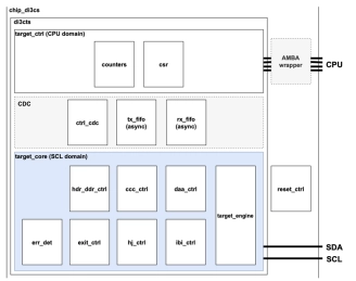
MIPI I3C Target Device
- MIPI I3C Basic Specification v1.2 compiliance
- Native 32-bit CPU Interface
- Optional CPU interface wrappers (APB, AHB, AXI)
- Legacy I2C communication with 7-bit Static Address
- I3C Single Data Rate (SDR) mode
-
MIPI SoundWire Slave Controller 1.2
- MIPI SoundWire®Slave Controller, typically integrated into audio DSP/Codecs or directly into audio peripherals such as Microphones and Amplifiers used in smart phones, tablets and mobile PCs.
- The IP when integrated provides SoundWire, a new audio interface to connect to Master typically embedded in Application Processor or Audio Codecs.
-
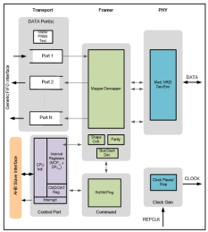
MIPI SoundWire Master Controller 1.2
- Compliant with MIPI SoundWire specification version 1.2
- Configurable number of Data Ports Configurable Direction – Source or Sink
- Implements clock gearbox with programmable frequency divider
- Implements SoundWire Bus Clock Stop and WakeUp detection