MIPI PHY IP
MIPI PHY IP IP solutions provide the physical layer communication for various MIPI interfaces, ensuring robust signal integrity and low-power operation. Key offerings include MIPI D-PHY IP, ideal for high-speed video and imaging applications, MIPI C-PHY IP, designed for optimized performance in mobile devices, and MIPI A-PHY IP, which supports automotive applications with long-range, high-speed capabilities. Additionally, the MIPI C-PHY/D-PHY Combo IP offers versatility for devices requiring both high-speed data and video transmission. With the MIPI M-PHY IP, advanced mobile and data storage solutions can achieve peak performance, making MIPI PHY IP a cornerstone for next-generation connectivity.
All offers in
MIPI PHY IP
Filter
Compare
428
MIPI PHY IP
from
32
vendors
(1
-
10)
-
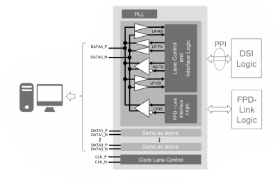
MIPI D-PHY and FPD-Link (LVDS) Combinational Transmitter for TSMC 22nm ULP
- Technology is TSMC 22nm ULP 1p10M.
- Supply voltage can be applied 1.0V for core voltage, 1.8V for IO voltage.
- Maximum data rate of each channel is 1.5Gbps at High-speed mode for MIPI D-PHY Transmitter.
- Data rate of each channel is 609Mbps for FPD-Link(LVDS).
-
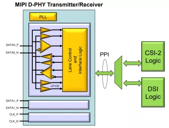
MIPI D-PHY Transmitter/Receiver for DSI/CSI-2 on Samsung 28nm FD-SOI
- Technology is Samsung 28nm FD-SOI 8M (6U1x_2T8x_LB).
- Supply voltage can be applied 1.1V for core voltage, 1.8V for IO voltage.
- Maximum data rate of each channel is 1.5Gbps at High-speed mode.
-
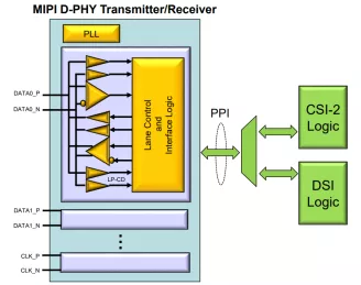
MIPI D-PHY Transmitter/Receiver for TSMC 40nm LP
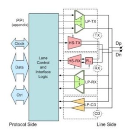
- Renesas MIPI D-PHY Transmitter/Receiver can be used for analog Transmitter/Receiver of following interface.
- Technology is TSMC 40nm LP 1p6M (4x1z) .
- Supply voltage can be applied 1.1V for core voltage, 1.8V for IO voltage.
-
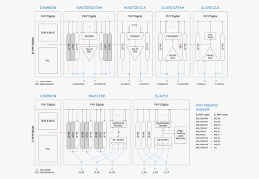
MIPI C/D-PHY Combo IP
- Compliant to MIPI D-PHY v3.0, C-PHY v2.1 specification
- Area efficient macro optimized for placement for dense SoC designs
- Support Uni-(TX or RX) and Bi-directional(TX and RX) mode
- Support emphasis architecture over lossy channel for TX
- Support equalize architecture over lossy channel for RX
-
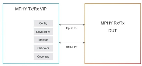
Simulation VIP for MIPI M-PHY
- Specification Compliance
- Complies with MIPI M-PHY 4.0, 4.1 and 5.0 specification
- M-PHY Type 1 and Type 2
- Supports Type 1 and Type 2
-
MIPI CSI2 Interface Solution
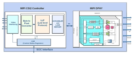
- Brite provides full solution for the MIPI CSI interface, which receives the data from sensors in PHY layer, and then converts the byte data to pixel after lane data mergence.
- Data scramble is an optional feature to decrease the EMI effect.
- A standard PPI interface is implemented for the connection between MIPI PHY and CSI controller. Brite MIPI CSI interface solution supports image applications with varying pixel formats.
-
MIPI D-PHY TX PHY and DSI controller
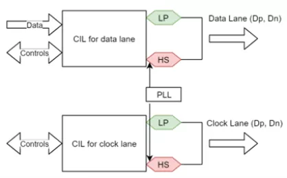
- Scalability and Flexibility: Supports multiple data lanes for higher aggregate bandwidth, any of the multiple lanes can be configured into Clock Lane
- High Data Rates: Supports data transmission rates up to 4.5Gbps per lane, allowing for high-resolution displays and smooth refresh rates
- Energy Efficiency: Optimized for low power consumption, making it ideal for battery-powered devices
- Complete Solution: Combines the MIPI D-PHY Transmitter PHY and DSI Controller to make it a one-stop solution
-
MIPI M-PHY® 4.1 Analog Transceiver
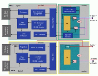
- The M-PHY is of Type 1, which apply to UFS, LLI, and CSI-3 protocols. The Multi-gear M-PHY 4.1 consists of analog transceivers, high-speed PLL, data recovery units as well as state-machine control — all in a single GDSII.
- The interface to the link protocol-specific controller (host or device) is compliant with the M-PHY RMMI specification, which allows seamless integration of the two IPs, namely the controller and the PHY, into the chip design.
-
MIPI D-PHY℠ v2.5 IP Core
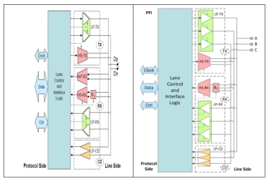
- This Tx/Rx transceiver complies with the MIPI Alliance C-PHY℠ v2.0 and D-PHY℠ v2.5 specifications, with world-class area and power dissipation, and is available for a range of foundry processes.
- This IP delivers 6 Gbps per lane for a max throughput of 24 Gbps in D-PHY℠ mode, and 6 Gsps per trio for a max throughput of 41.04 Gbps in C-PHY℠ mode.
-
MIPI D-PHY v2.1 IP Core
- Compliant to MIPI® Alliance Standard for D-PHY specification Version 2.1
- Supports D-PHY 1.1 synchronous transfer mode at high speed mode with a bit rate of 80-1500 Mb/s without deskew calibration
- Supports DPHY 1.2 for 1500 – 2500 Mb/s with deskew calibration.
