UPF Constraint coding for SoC - A Case Study
By Nikila S, Poornimadevi S, Thevin Arokiaraj L (HCL Technologies, Chennai)
1. Abstract
With the rise in power consumption and data-intensive processing required for modern applications such as IoT, Deep Learning and Image processing, there is a growing need of an optimal power optimization that is to be employed by low power design engineers and for this purpose, the Unified Power Format(UPF) standard is used to specify and verify the power intent of SoC (System on Chip) design. Over the years, the UPF standard has advanced to provide avant-garde features for the industry to develop optimal power design techniques. This paper deals with the implementation of UPF for low power SoC design that can encompass several vendor IPs and custom IPs UPF constraints.
Keywords: UPF, Low Power Design, VLSI, System On Chip (SoC), Power domains, Isolation, Retention strategy, Intellectual Property (IP), IEEE
2. Introduction
Reduction and optimization of power consumption in modern-grade electronics is one of the biggest challenges that the VLSI industry is facing with the increasing uptrend of usage of both consumer-grade and industry-grade electronics for medical, computational, analytical and military purposes. This has led to the research and development of low power methods that needs to be employed in power-critical components. Low Power strategies such as Clock gating, Power gating, Dynamic Voltage and Frequency Scaling (DVFS), Isolation and Retention provide optimal power optimizations to the SoC. The IEEE 1801 United Power Format (UPF) is an evolving standard for specifying the power intent used to define power management and to minimize power consumption in Semi-Custom SoC design. This paper deals with specifying UPF for an SoC under the assumption that it only contains a single Voltage domain with multiple switchable power domains.
Section 3 of this paper deals with the various components of UPF standard that specify the low power constraints and configuration for HDL design. Section 4 discusses an example low power SoC design architecture for which the UPF constraints will be specified. Section 5 and Section 6 explains the Subsystem-level and Top-level UPF flow respectively. Section 7 deals with some specific issues faced during UPF linting and solutions for these issues.
3. Components of UPF
The UPF specification requires the name and the number of power domains, the element containing the design instances that are to be grouped under a specific power domain, power state table that will list all the combination of states for the supply set and the power domain for the IP/Elements, memories or registers that need to be retained. Based on the UPF specification, the following constructs are used to design the UPF constraints:
3.1. Design Scope
The design scope specifies the instance name of the hierarchical top-level module and the specified UPF constraints are only applicable to the instance defined in the design scope. The design scope can be specified by the set_scope command.
3.2. Load UPF
Load UPF command loads the IP UPF constraints in Subsystem UPF file for the IP instance name mentioned in the set_scope or this command loads the subsystem UPF constraints in SoC Top UPF file for the Subsystem instance name mentioned in the set_scope.
3.3. Power Domain
Power domain defines the group of instances that shares the common set of power supply requirements.
3.4. Supply Ports
Supply Nets are connected to supply ports from which the domain elements can draw power from.
3.5. Supply Nets
Supply net provides voltage supply to the power domain elements via a supply port.
3.6. Power Switch
Power switches are created for providing power-shutdown functionality when its associated power domain transitions to a low power state.
3.7. Supply Set
The primary and ground functions are combined to provide a complete power supply source. The primary supply can be power switch output or supply nets or ports.
3.8. Power State
Power state defines the state of the supply set or the power domain. Typical power states include ON, OFF, RETENTION and HIBERNATION states.
3.9. Isolation Strategies
When two domains interact, isolation cells must be inserted at the input or the output of the domain interface to prevent the propagation of unknown values when the power supply is removed for one power domain.
3.10. Retention Strategies
Retention strategy for a domain element is employed to retain the state when the associated power domain is in retention mode. This allows the associated elements to resume quickly for normal operation as it does not need to be reset after a power cycle.
3.11. Level Shifters
Level Shifters are used when the driving and the receiving supply ports have different voltage values. Level shifters are applied at the domain boundary to correct the voltage differences.
4. Low Power Design Architecture
A small SoC design example is used as reference to convey various points mentioned in this paper. The diagram below shows the different power domains that are supported in the Example SoC design. The Example SoC operates on a single voltage domain. Each subsystem, along with its sub-level components, consists of Power Domain crossing Bridge whose Master and Slave modules will be placed in different power domain for handling power domain crossing.

Click to enlarge
Figure 1 Low Power SoC Block diagram
Note: M1-M11 are different modules/IPs instantiated in each sub-system
Two different approaches can be followed while constructing the SoC UPF file:
Top-Down Approach: In this approach, a single UPF constraint file is maintained for entire SoC design. Here, a single scope will be utilized for all the power domains and that is placed in the top level scope. This will save the effort of creating multiple supply ports and connecting the power supply network since all of the supplies that needs to be handled are present in the top-level scope. This SoC constraint UPF file for this approach contains the following:
- Instance/elements are grouped under each power domain in the SoC.
- Create power domains for each grouped instances with supply set.
set $PD_IB_GROUP {list subsystem1/Power_Domain_Crossing_Bridge/Master
subsystem2/Power_Domain_Crossing_Bridge/Master
subsystem3/Power_Domain_Crossing_Bridge/Master
subsystem5/Power_Domain_Crossing_Bridge/Master
Interconnect Bus}
create_supply_set IB_SS
create_power_domain PD_IB -supply {primary IB_SS} -elements “$PD_IB_GROUP”
Similarly group other subsystem elements for each power domains
- Create logic nets for isolation, retention and power enable signals for all power domains and connect those nets with the corresponding ports of power controller.
create_logic_net m1_pwr_en
connect_logic_net m1_pwr_en –ports {subsystem1/M1_power_controller/m1_pwr_en}
Similarly connect other logic nets with the ports of power controller
- Retention strategy can be implemented for memories or registers that needs to be retained in the design.
- Isolation cells are inserted at the output of all switchable power domains with clamp value ‘0’ for active-high signals and ‘1’ for active-low signals.
- Power state for each power domain with logic and supply expression is defined.
| Power Domain | Power State | ||
| ON | OFF | RETENTION | |
| PD_M1 | ON | OFF | OFF |
| PD_M2 | ON | OFF | OFF |
| PD_M3 | ON | OFF | OFF |
| PD_M4 | ON | OFF | RET |
| PD_M5 | ON | OFF | OFF |
| PD_M6 | ON | OFF | OFF |
| PD_M8 | ON | OFF | OFF |
| PD_M11 | ON | OFF | RET |
| PD_IB | ON | OFF | OFF |
Table 1 Power State Tables for SoC
- Power switch is created for every switchable power domains.
Bottom-Up Approach: A separate UPF constraint file can be created for each subsystem and all the subsystem UPF files are loaded in the SoC Top UPF file using load_upf command with set_scope specifying the corresponding instance name. In Bottom-UP approach each subsystem RTL plus its corresponding UPF intent can be verified separately and does not require a full SoC Top constraint for low power linting. Here, multiple scope will be utilized for all the power domains by loading each subsystem UPF constraints for each scope in the top level UPF file. The detailed UPF flow for this approach is explained in the Section 6.
5. Subsystem Level UPF implementation
This section covers the different approach followed in UPF implementation at Subsystem Level. Subsystem3 Example is used to showcase top-down approach and Subsystem1 Example is used to showcase bottom-up approach for specifying power strategies.
5.1. Subsystem3 Top Design
Consider the below Subsytem3 Top design that follows the top-down approach. In top down approach, the constraints are developed from the parent instance.
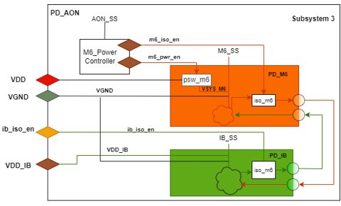
Figure 2: Power strategy for Subsystem 3
The tree diagram for AI Core top hierarchy is shown below:
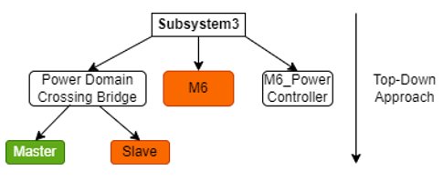
Figure 3: Tree diagram for Subsystem3
Subsytem3 hierarchical top consists of three power domains: PD_M6, PD_AON and PD_IB. PD_M6 contains the AI Core IP (this can be any functional IP like ARM processor core etc.), SRAM and the Slave block of Power domain crossing bridge. PD_IB contains the Master block of Power domain crossing bridge. PD_AON consists of M6_Power_controller, which essentially controls the switching ON or OFF of PD_M6 power domain using the generated power control signal and it also generates enable signals for isolation control. IB_Power Controller placed in SoC Top-level, handles PD_IB switchable power domain in Subsystem3. Isolation cells are generally placed for signals that cross from a switchable power domain to another power domain.
With the power strategy in place, the power state table for Subystem3 follows below:
| Power Domain | Power State | ||
| ON | OFF | RETENTION | |
| PD_M6 | ON | OFF | OFF |
| PD_IB | ON | OFF | OFF |
Table 2 Power State Table for AI Core
5.1.1. Subsystem3 Top UPF
Now the power state table and power strategy has been drawn up, the UPF flow construct for the AI core subsystem design has been listed below:
Supply sets are created for PD_M6 and PD_IB power domains.
create_supply_port VDDcreate_supply_net VDD
connect_supply_net VDD -ports VDD
create_supply_port VGND
create_supply_net VGND
connect_supply_net VGND -ports VGND
create_supply_net VSYS_M6
connect_supply_net VSYS_M6 -ports VSYS_M6
create_supply_port VSYS_IB
create_ supply_set M6_SS -function {power VSYS_M6} -function {ground VGND}
create_ supply_set AON_SS -function {power VSYS} -function {ground VGND}
create_ supply_set IB_SS -function {power VSYS_IB} -function {ground VGND}
Power domain
- Create PD_M6, PD_IB, PD_AON power domains with the respective elements and supply sets.
- Create the default power domain PD_AON using –include_scope option in the create_power_domain command.
create_power_domain PD_M6 -supply {primary M6_SS} -elements {M6}
create_power_domain PD_AON -supply {primary AON_SS} -include_scope
create_power_domain PD_IB -supply {primary IB_SS} -elements {AB/MASTER}
Set port attributes
- Subsystem3 top level output ports are to be specified with –receiver_supply set and Subsystem3 top level input ports will have to be specified with –driver_supply set using set_port_attributes command.
set_port_attributes -ports "$SUBSYSTEM3_INPUT_PORTS" -driver_supply IB_SS
set_port_attributes -ports "$SUBSYSTEM3_OUTPUT_PORTS" -receiver_supply IB_SS
Subsystem3 inputs are driven by Interconnect Bus and the outputs are received by Interconnect Bus.
Logic ports and logic nets
- Logic nets are created for isolation and power enable signals and are connected to the ports of M6_Power_Controller using connect_logic_net command.
create_logic_net m6_pwr_en
connect_logic_net m6_pwr_en –ports {M6_power_controller/m6_pwr_en}
create_logic_net m6_iso_en
connect_logic_net m6_iso_en –ports {M6_power_controller/m6_iso_en}
- Logic ports and nets are created for isolation and power enable signals of PD_IB power domain and the nets are coupled with the created ports.
create_logic_port ib_pwr_en
create_logic_net ib_pwr_en
connect_logic_net ib_pwr_en –ports ib_pwr_en
create_logic_port ib_iso_en
create_logic_net ib_iso_en
connect_logic_net ib_iso_en –ports ib_iso_en
Isolation Cells
- Isolation cells are placed at the output of PD_M6 and PD_IB domains. Retention cells are not needed as RETENTION power mode is not supported in module6.
set_isolation iso_m6 -domain PD_M6 -applies_to outputs -clamp_value 0 -location self\
-isolation_signal {m6_iso_en} -isolation_sense high -isolation_supply_set AON_SS
set_isolation iso_ib -domain PD_IB -applies_to outputs -clamp_value 0 -location self\
-isolation_signal {ib_iso_en} -isolation_sense high -isolation_supply_set AON_SS
Power states
- Logical and supply expressions of power states are created based on the power state table and supply set respectively for both PD_M6 and PD_IB power domains.
add_power_state PD_M6 -state SYS_ON {-logic_expr {m6_pwr_en == 1 && m6_iso_en == 0 }} \
-state SYS_RET {-logic_expr {m6_pwr_en == 0 && m6_iso_en == 1 }} \
-state SYS_OFF {-logic_expr {m6_pwr_en == 0 && m6_iso_en == 1 }}
add_power_state PD_IB -state SYS_ON {-logic_expr {ib_pwr_en == 1 && ib_iso_en == 0 }} \
-state SYS_RET {-logic_expr {ib_pwr_en == 0 && ib_iso_en == 1 }} \
-state SYS_OFF {-logic_expr {ib_pwr_en == 0 && ib_iso_en == 1 }}
add_power_state M6_SS -state ON {-supply_expr {power == `{FULL_ON 1.09} && ground == `{FULL_ON 0.0}}}\
-state OFF {-supply_expr {power == `{OFF} && ground == `{FULL_ON 0.0}}}
add_power_state AON_SS -state ON {-supply_expr {power == `{FULL_ON 1.09} && ground == `{FULL_ON 0.0}}}
add_power_state IB_SS -state ON {-supply_expr {power == `{FULL_ON 1.09} && ground == `{FULL_ON 0.0}}}\
-state OFF {-supply_expr {power == `{OFF} && ground == `{FULL_ON 0.0}}}
Power Switch
- Power switch for the PD_M6 power domain is created.
create_power_switch SW_M6 -input_supply_port {VIN VDD}
-output_supply_port {VOUT VSYS_M6}
-control_port {LEN m6_pwr_en}
-on_state {ON VIN {LEN}\
-off_state {OFF {!LEN}}
-domain PD_M6
Similarly, create UPF files for Subsystem2, 4 and 5.
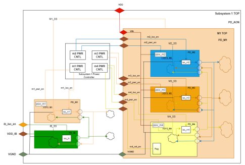
5.2. Subsystem1 Top DesignThe below subsystem1 design diagram follows the bottom-up approach for specifying power strategies. In Bottom-Up Approach, UPF constraints are developed from the child instance (M1 IP) which means the UPF file is first constructed for M1 IP.
Click to enlarge
FIGURE 4: Power strategy for Subsystem1
The tree diagram for Subsystem1 top hierarchy is shown below:

FIGURE 5: Subsystem1 Tree diagram
Subsystem1 consists of M1 IP, Power Domain Crossing Bridge and the Power controller. M1 IP hierarchical top consists of four power domains: PD_M1,PD_M2, PD_M3 and PDM4. M2 and M3 contains the data processing unit with instruction and data cache. Debug logic and the other remaining logic are included under PD_M1 power domain. PD_M1 is the default power domain for M1 IP. Power Domain Crossing Bridge contains slave and master that are placed in PD_M1 and PD_IB power domains respectively. Power controller is placed in the Always-ON power domain(PD_AON), which essentially controls the switching ON or OFF of all the power domains present inside the subsystem1.
5.2.1. Subsystem1 Hierarchical UPF
As mentioned in the above section, that subsystem1 UPF follows the bottom-up approach with the IP vendor provided constraints UPF file for M1 IP (child instance). Based on the constraints file, configuration, implementation UPF files needs to be developed.
Constraints UPF file defines the
- Power domains and the IP elements associated with the power domains.
- Elements that are need to be retained by the IP.
- Isolation clamp value is specified for elements or domains or input/output ports.
- Power state strategy is provided for supported power domains by the IP.
Configuration UPF file contains the following
- Logic nets and ports for isolation enable and power enable signals for all the power domains.
- Isolation and Retention strategies are specified based on the constraints file.
- Power state with supply expression is specified with its voltage level during ON and OFF.
Implementation file defines
- How the power supply should be distributed to the IP, so the supply nets and ports are created for all power domains.
- Power switch strategy for each domain is specified based on the power enable signal in the configuration UPF file.
The Constraints, Configuration, Implementation UPF files are loaded in the subsystem1 Top UPF file. In addition to this the remaining modules (Power controller and Power Domain Crossing Bridge) constraints are added in the Subsytem1 Top UPF file.
Subsystem1 TOP UPF File:
- Set the scope with the M1 IP instance name. Load and initiate the M1 IP UPF file.
set_scope m1_ip
load_upf m1_ip_constraints.upf
load_upf m1_ip_configuration.upf
load_upf m1_ip_implementation.upf
- Now set the scope to the subsystem1 Top level
set_scope /
- Define the supply nets and ports for subsystem1 top and connect to the IP level supply port
create_supply_port VDD
create_supply_net VDD
connect_supply_net VDD -ports VDD
create_supply_port VGND
create_supply_net VGND
connect_supply_net VGND -ports VGND
connect_supply_net VDD -ports m1_ip/VDD
connect_supply_net VGND -ports m1_ip/VGND
- Define the connection for IP level logical ports with the Power controller
connect_logic_net m0_pwr_cntl/m0_iso_en -ports m1_ip/m0_iso_en
connect_logic_net m0_pwr_cntl/m0_pwr_en -ports m1_ip/m0_pwr_en
connect_logic_net m1_pwr_cntl/m1_iso_en -ports m1_ip/m1_iso_en
connect_logic_net m1_pwr_cntl/m1_pwr_en -ports m1_ip/m1_pwr_en
connect_logic_net m2_pwr_cntl/m2_iso_en -ports m1_ip/m2_iso_en
connect_logic_net m2_pwr_cntl/m2_pwr_en -ports m1_ip/m2_pwr_en
connect_logic_net m2_pwr_cntl/m2_ret_en -ports m1_ip/m2_ret_en
connect_logic_net m3_pwr_cntl/m3_iso_en -ports m3_ip/m3_iso_en
connect_logic_net m3_pwr_cntl/m3_pwr_en -ports m3_ip/m3_pwr_en
- Define the Supply set for IB and M1 power domain
create_supply_net VSYS_M1
connect_supply_net VSYS_M1 -ports VSYS_M1
create_supply_port VSYS_IB
create_ supply_set M1_SS -function {power VSYS_M1} -function {ground VGND}
create_ supply_set AON_SS -function {power VSYS} -function {ground VGND}
create_ supply_set IB_SS -function {power VSYS_IB} -function {ground VGND}
- Connect the supply net VSYS_M1 to IP level supply ports of PD_M1 power domain
connect_supply_net VSYS_M1 -ports m1_ip/VSYS_m1
- Define the Power domain for Asynchronous Bridge (AB) and Power controller that is present in the Subsystem1.
- Subsystem1 top level output ports are to be specified with –receiver_supply set and top level input ports will have to be specified with –driver_supply set using set_port_attributes command.
- Define isolation Strategy for IB power domain (To clamp the master output ports of Power domain crossing bridge) and isolation Strategy for M1 power domain (To clamp the slave output ports of Power domain crossing bridge)
- Define Power states with supply and logical expression for IB power domain
- Define Power switch for PD_M1 power domain and output supply net is VSYS_M1
The below SoC Top design follows the bottom-up approach for specifying power strategies. All subsystem level blocks are designed and verified separately. Top level UPF file can be implemented using the multiple UPF file.

Click to enlarge
FIGURE 6: Power strategy for SoC Top
The tree diagram for SoC top hierarchy is shown below:
Click to enlarge
FIGURE 7: SoC Top Hierarchy Tree diagram
SoC TOP Level UPF file:
- Set the scope for each subsystem with instance name and load the corresponding UPF file.
set_scope subsystem1
load_upf subsystem1.upf
set_scope /
set_scope subsystem2
load_upf subsystem2.upf
set_scope /
set_scope subsystem3
load_upf subsystem3.upf
set_scope /
set_scope subsystem4
load_upf subsystem4.upf
set_scope /
set_scope subsystem5
load_upf subsystem5.upf
set_scope /
- Define the supply nets and ports for providing main supply to SoC top and connect to each Subsystem level supply port
connect_supply_net VDD -ports subsystem1/VDD
connect_supply_net VGND -ports subsystem1/VGND
Similarly connect the VDD and VGND to all subsystem ports
- Define the connection for subsystem level logical ports of PD_IB with IB Power controller
connect_logic_net ib_pwr_cntl/ib_iso_en -ports subsystem1/ib_iso_en
connect_logic_net ib_pwr_cntrl/ib_pwr_en -ports subsystem1/ib_pwr_en
Similarly connect the ib_iso_en and ib_pwr_en ports of all subsystem with IB power controller ports
- Define the Supply nets, ports and set for Always ON and IB power domain
- Connect the IB power domain supply net to subsystem level IB supply ports of PD_IB power domain
connect_supply_net VSYS_IB -ports subsystem1/VDD_IB
Similarly connect the VDD_IB ports of all subsystem with the VSYS_IB supply port in top
- Define the Power domain for IB that is present in the SoC top and remaining logic are included under PD_AON (default power domain).
- Create power switch, power state strategy for PD_IB power domain
- Define isolation Strategy for IB power domain (For PD_IB output ports that is received by Always ON power domain)
7. Design Scenarios, Issues and Resolution
This section covers the different issues observed and their resolution. Cadence Conformal Low Power LEC tool was used for Low Power Linting on UPF file. UPF itself followed UPF 2.1 standard version
7.1. Dealing with splitting of ports
The output port A in the below diagram sink to two modules, one with same supply set(M6_SS) and other with different supply set(M5_SS).
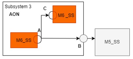
FIGURE 8 Port splitting to different supply set
In the following example, isolation strategy is applied to the crossing ports between supply set M6_SS and M5_SS. In the below command, isolation location is mentioned as “self” that results in Isolation Cell placed at the output port “A”.
set_isolation iso_out -domain PD_M6 \
-isolation_supply_set AON_SS \
-clamp_value 0 \
-applies_to outputs \
-isolation_signal devisolaten \
-isolation_sense high \
-source M6_SS \
-sink M5_SS \
-location self
This means the ports B and C will be clamped to value ‘0’. However, the port C doesn’t need to be clamped because the ports A and C are having the same supply set. This results in the following issue,
1801_STRATEGY_NON_IMPLEMENTABLE: Strategy implementation would require modifications to the design that are not allowed.
Error: Power_Intent/subsystem3.upf: Strategy 'iso_out' is not implementable at lowconn of element 'ai_ip/A'
Solution: Change the –location option from self to parent so that the isolation is placed at port B of parent instance.
7.2. Dealing with inconsistent receiver/driver supply sets
In the below diagram, the port B is having M1_SS as the receiver supply set. When running subsystem1 UPF along with the Subsystem1 RTL file separately, there will be no errors because the tool will apply the receiver supply constraint for port B and it will not check whether the Port B is received by M1_SS or not. However, while running SoC Top, the tool will check the Port B receiver supply set constraint with the receiving logic of port C supply set.
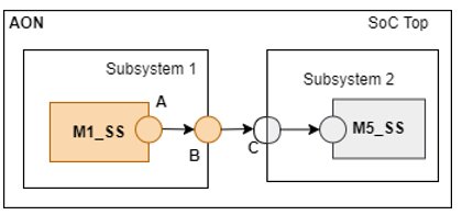
FIGURE 9: Inconsistent supply set example1
The Subsystem1 UPF receiver supply constraint for port B is defined below :
set_port_attributes –ports {B} –receiver_supply M1_SS
When checking the consistency between the receiver supply set of port B versus the supply set of port C, the tool reports the following errors:
1801_SUPPLY_ATTR_DESIGN_CONFLICT:
Error: Port 'Subsystem1/B' is received by port 'Subsystem2/C' with supply set 'M5_SS', but an inconsistent receiver supply 'Subsystem1/M1_SS' (representative: 'M1_SS') is specified by 'set_port_attributes'.
Solution: The above conflict must be resolved by changing the –receiver_supply option from M1_SS to M5_SS and by placing isolation cells between port A and port B.
However, for the below case the same conflict error can be waived off.
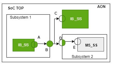
FIGURE 10: Inconsistent supply set example2
The above illustration depicts port B with IB_SS as receiver supply set in Subsystem1 and port D is having driver supply of IB_SS are specified using set_port_attributes command. Isolation is placed between port D(IB_SS) and M5_SS. While running Soc Top, the tool reports the following error :
1801_SUPPLY_ATTR_DESIGN_CONFLICT
Error: Port 'Subsystem1/B' is received by port 'Subsystem2/M5/E with supply set 'M5_SS', but an inconsistent receiver supply 'IB_SS' (representative: 'IB_SS') is specified by 'set_port_attributes'.
Solution: This error can be waived off because isolation has already been implemented between port D(IB_SS) and E(M5_SS).
7.3. Dealing with Top Level Boundary ports
Port B and port D in the below diagram are having AON_SS supply set and isolation is placed between port A(IB_SS) and port B(AON) and as well as between the port C(IB_SS) and port D(AON_SS). While running Subsystem3 and Subsystem2 UPF files separately, no warnings are logged.

FIGURE 11: Top Level Boundary Ports supply set connections
However, while triggering SoC top UPF linting the following warning is encountered:
Warning: 1801_STRATEGY_NO_EFFECTIVE_ELEMENT: Strategy does not apply to any design instances or ports Power_Intent/subsystem2.upf:54 Strategy 'PD_M5.ISO' has no effective elements
Since there is no OFF to ON crossings between ports B and E then the ports D and F and the specified ports are in AON_SS, this warning is logged.
Solution: This warning can be cleared by specifying the receiver and driver supply for ports B , E , D and F as IB_SS supply set using set_port_attributes command.
7.4. Dealing with Clamp Value Conflicts

FIGURE 12: Clamp Value Conflict
In RTL, port A is assigned to a constant value(‘b1) that is driving ports B and C but in UPF, isolation is placed at the output of M1 power domain with clamp value 0. Due to this conflict between RTL and UPF, the below error occurs:
1801_ISO_CLAMP_VALUE_CONFLICT: Isolation strategy clamp value conflicts with driver constraint value
Error: ‘M1/PD_M1.iso1’ specifying clamp value '0' conflicts with the propagated tied value '1' at highconn of element 'M1_top/M2/B'
Error: ‘M1/PD_M1.iso2’ specifying clamp value '0' conflicts with the propagated tied value '1' at highconn of element 'M1_top/M3/C'
Solution: These errors can be resolved by adding –exclude_elements options for port A in iso1 strategy command and set a separate isolation strategy for port A with clamp value 1.
7.5. Dealing with floating ports
Isolation will be placed at the output of the particular power domain which also includes the unconnected ports. However, floating ports don’t require isolation because those ports don’t drive any logic in the RTL.
Case 1:

FIGURE 13 Isolation at outputs that sink to same supply set
Case 2:

FIGURE 14 Isolation at outputs that sink to different supply set
For both the cases, isolation strategy is placed at the output of PD_SS1 power domain, so it is placed at all three ports A, C, B (floating port).
set_isolation iso_out -domain PD_SS1 \
-isolation_supply_set AON_SS \
-clamp_value 0 \
-applies_to outputs \
-isolation_signal devisolaten \
-isolation_sense high \
-location self
This results in the following issue.
1801_ISO_FLOATING_OUTPUT: Isolation strategy inserts an isolation cell driving a floating output
There is no receiver connected from the output pin of virtual inserted ISO cell 'top/ss1/B' with strategy 'top/PD_SS1.iso_out’
This can be resolved by specifying the -sink SS2 in isolation cell for the case1 and -diff_supply_only TRUE option for case2 in the isolation strategy in , since the floating port is not connected to any supply, it does not match a sink or diff_supply_only filter.
8. Best Practices to be followed while writing a UPF file
- Use variables using set command to group the elements/ports.
Example: Group the instance using variable (i.e MEM_ELEMENTS) to create the power domain (PD_MEM) with Supply set (MEM_SS) for the below design.

Figure 15: Instance Grouping Using Variable
set MEM_ELEMENTS {TOP/M1/MEM1
TOP/M1/MEM2
TOP/M1/MEM3}
create_power_domain PD_MEM -supply MEM_SS -elements “$MEM_ELEMENTS”
- Top level output ports must be specified with receiver supply set and Top level input ports must be specified with driver supply set.
Example: UPF is constructed for M1 Top Module with following I/O constraints.

Figure 16: M1 TOP I/O ports Supply Sets
set M1_IN_PORTS {A B C}
set M1_OUT_PORTS {D E}
set_port_attributes “$M1_IN_PORTS” -driver_supply CORE_SS
set_port_attributes “$M1_OUT_PORTS” -receiver_supply MEM_SS
- Clamp value must be ‘0’ for active-high signal and ‘1’ for active-low signal.
Example: consider output Port D is active HIGH and Port E is active LOW Signals. So set isolation for two ports separately.
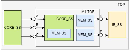
Figure 17: Isolating Active HIGH and Active LOW ports
set_isolation iso1 -domain PD_MEM -elements{M1 TOP/D} -clamp_value 0 -location self\-isolation_signal {iso_en} -isolation_sense high -isolation_supply_set AON_SS
set_isolation iso2 -domain PD_MEM -elements{M1 TOP/E} -clamp_value 1 -location self\
-isolation_signal {iso_en} -isolation_sense high -isolation_supply_set AON_SS
- Following order should be followed while defining the constraints in UPF file:
- Create supply port, nets and supply sets
- Define the receiver and driver supply set for all the top level boundary ports
- Create power domain
- Create set_port_attributes constraints for Top level ports with Driver/Receiver Supply sets and for the isolation with clamp value.
- Create logic port for isolation enable, power enable and retention enable signals
- Retention Strategy and Isolation strategy is created.
- Power state is defined with logical and supply expressions.
- Power switch is created.
9.Conclusion
In conclusion, we have seen the different UPF constructs that can be implemented for a low power design. Also discussed about the construction of UPF file for each subsystem by following the Bottom-Up or Top-Down approach. We have seen the implementation of a SoC Top UPF file with multiple UPF files of all Subsystem in a SoC. In addition to this, debug design scenarios like port splitting, floating port, supply set and clamp value conflict are also discussed in this paper.
10. References
- Article “Low Power Design in SoC using ARM IP”
- Unified Power Format (UPF 2.1) Standard: IEEE standard for design and verification of low power integrated circuits. IEEE 1801™ (March 27, 2009).
- IEEE 1801 User Guide, Product Version 14.1, June 2014, Cadence.
- Article “UPF Power Domains and Boundaries”, https://semiengineering.com/upf-power-domains-and-boundaries/
- ITRS (The International Technology Roadmap for Semiconductors): 2011 Edition.
- Synopsys Low-Power Flow User Guide, Synopsys.
- Dominik Macko et al., “Simplifying low-power SoC top-down design using the system-level abstraction and the increased automation, Integration”, iedec 2018, Pages -101 to 114.
- Naveen Kumar Challa et al., “The New Era on Low Power Design and Verification Methodology”, International Journal of Advances in Science Engineering and Technology, ISSN: 2321-9009 Volume- 4, Issue-3, Jul.-2016.
- Emilie Garat et al., “Unified Power Format (UPF) methodology in a vendor independent flow”, 2015 25th International Workshop on Power and Timing Modeling, Optimization and Simulation (PATMOS), 2015, pp. 82-88.
Related Semiconductor IP
- HBM4 PHY IP
- Ultra-Low-Power LPDDR3/LPDDR2/DDR3L Combo Subsystem
- MIPI D-PHY and FPD-Link (LVDS) Combinational Transmitter for TSMC 22nm ULP
- HBM4 Controller IP
- IPSEC AES-256-GCM (Standalone IPsec)
Related Articles
- FeNN-DMA: A RISC-V SoC for SNN acceleration
- Formal Property Checking for IP - A Case Study
- A RISC-V Multicore and GPU SoC Platform with a Qualifiable Software Stack for Safety Critical Systems
- SV-LLM: An Agentic Approach for SoC Security Verification using Large Language Models
Latest Articles
- ElfCore: A 28nm Neural Processor Enabling Dynamic Structured Sparse Training and Online Self-Supervised Learning with Activity-Dependent Weight Update
- A 14ns-Latency 9Gb/s 0.44mm² 62pJ/b Short-Blocklength LDPC Decoder ASIC in 22FDX
- Pipeline Stage Resolved Timing Characterization of FPGA and ASIC Implementations of a RISC V Processor
- Lyra: A Hardware-Accelerated RISC-V Verification Framework with Generative Model-Based Processor Fuzzing
- Leveraging FPGAs for Homomorphic Matrix-Vector Multiplication in Oblivious Message Retrieval