Reusable Test-Case Methodology for SoC Verification
Ganesh Venkatakrishnan, Open-Silicon Research Private Limited
Abstract
This paper proposes a novel Test-Case methodology for System on chip (SoC) Verification in order to achieve high levels of reusability. It surveys the challenges of a traditional SoC Test-Case Methodology and then proposes a solution.
I. INTRODUCTION
The paper starts with giving an introduction to a traditional SoC Test-Case Methodology, commenting on its benefits and inherent limitations. The rest of the paper introduces the reader to a novel approach to SoC Test-Case Methodology. It also provides a sample implementation that can be modified or enhanced based on SoC needs.
The idea presented here is matured and deployed in live SoC projects.
II. TRADITIONAL SOC TEST-CASE METHODOLOGY
A typical SoC Verification cycle involves driving the Processor transactions using a Bus VIP in the initial phase. With the advent of System Verilog and Verification methodologies (UVM, VMM, OVM etc.), driving transactions through a Bus VIP offers a lot of flexibility in test coding and also provides flexibility to control the kind of traffic being generated, which otherwise can be a tedious effort with the Processor in place. But the Bus VIP based approach has its own limitations that it models the Bus and not the system. It cannot verify interrupts, interrupt service routines (unless checked explicitly in the test-case).
Processor based tests are coded late in the Verification cycle, where only few of the existing test-cases (say in System Verilog) are ported to a language (typically C) that can be converted into a binary (using a cross compiler) for the Processor to execute. Processor booting, interrupts, interrupt service routines (ISRs) and SoC use cases are verified in this phase.
This paper proposes a Test-Case Methodology where, one can reap the benefits of using the Bus VIP in the initial phase but can also seamlessly port them directly to the Processor based setup without much effort.
III. PROPOSED SOC TEST-CASE METHODOLOGY
The proposed Test-Case Methodology provides a reusable setup to be able to execute test cases at Bus VIP Level or at Processor Level.
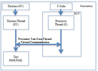
The proposed approach is based on “Processor Modeling”. In this approach, every test case consists of 2 threads:
- Processor Thread coded in C, which the Processor or the Processor-Model will execute
- Test Case Thread coded in System Verilog

Figure 1: Reusable Test-Case Methodology for SoC
The Test Case thread (SV code) addresses the following aspects of a Simulation:
- Controlling all transactions to the SoC through the peripheral TB components (or VIPs).
- Synchronizing drivers based on the user defined code received from the Processor from the Virtual Communication channel (GPIO, Scratch Pads etc.)
- Deciding Test Case PASS or FAIL criteria.
The Processor thread (C code) addresses the following aspects of a Simulation:
- Executing Processor Main function that configures the DUT for a particular test scenario.
Executing Interrupt Service routines for corresponding Interrupt IDs whenever an Interrupt occurs.
The thread communication between the 2 threads may be a virtual communication. Some of the possible options are to use:
- GPIO Pins can be written by the Processor thread with specific user defined codes that can be understood by the Test Case thread.
- Spare registers (Scratch Pad registers) in design can be used for the same purpose.
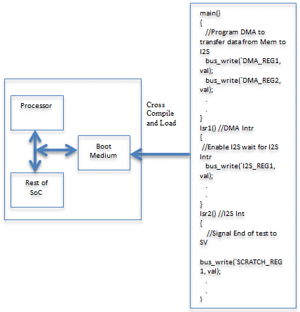
When Using Processor:
When running tests using Processor, the C code is cross compiled and converted into a Hex file and loaded into the Boot Medium (ROM, System Memory or External Flash). The Processor will start executing the Hex Code from the Boot Medium. The interrupts will be serviced according to the ISR-Interrupt ID mapping specified in the Interrupt Handler routine.

Figure 2: SoC Test-Case Methodology with Processor in place
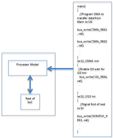
When Using Processor Model (with Bus VIP):
The proposed approach uses a simple Processor Model that can execute the C Code just like how a Processor would do.
The Processor model must address the following aspects at a higher level:
- The Processor Model must start executing the Main function in the C Code at reset
- It must also service interrupts based on the Interrupt ID mapping defined for the SoC
Thus the same Test-Case can be run with or without Processor with minimum effort. The only effort is to create a switchable Flow to replace the Processor with the Processor Model in the simulations.
A simple Processor Model can be coded with the use of Programming Language interface (PLI) or System Verilog Direct Programming Interface (DPI). A sample implementation using DPI has been provided in the next section.

Figure 3 SoC Test-Case Methodology with Bus VIP based Processor Model in place
IV. SAMPLE IMPLEMENTATION OF PROCESSOR MODEL
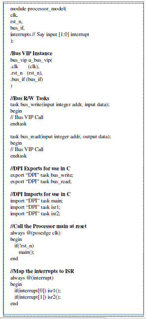
In this section, a snapshot of the Processor Model implementation has been demonstrated. The sample implementation uses System Verilog Direct Programming Interface (DPI) to model the Processor.
As mentioned in the previous section, the two factors that need to be considered by the Processor Model are:
- Processor Main function that is executed at reset
- Interrupt Service Routine execution
The sample code (in Figure 4) uses a Bus VIP for driving the transactions at the interface. There are predefined Bus Read/Write tasks to perform the same. These R/W tasks are exported to be used by the C-code which is executed as the Processor thread.
Similarly the Processor Main and ISRs are imported to be called directly by the Simulation thread.
This code can be enhanced with advanced capabilities to service interrupts on level or edge triggered basis.
The Processor Model core can be kept common across SoCs that share Processors with the same Bus Interface.

Figure 4: Sample implementation of Processor Model
V. SWITCHING BETWEEN PROCESSOR AND PROCESSOR-MODEL SETUPS
The flow used to Switch between Processor and Processor-Model setups is left for the user to decide.
Although, the following options may be explored:
- Use externally controlled ‘define’ Macros in RTL to choose Processor/Processor-Model
- Maintain an automated File-list Management system which can switch the Processor File-list with the Processor-Model File-list. In this case the Processor-Model must have the same module name and port list for seamless switching.
- Users may also explore Auto generation of the Processor Model wrapper to map the ISRs to the Interrupt ID based on a simple text format.
VI. ADVANTAGES OF REUSABLE TEST-CASE METHODOLOGY
Advantages of the proposed Test Case Methodology is
- Separate efforts are not required to code Processor based test cases
- Test Case models the system irrespective of whether the test is running on Processor/Bus VIP based setup.
- Ability to switch between Bus VIP and Processor based setups seamlessly.
- Enables Interrupts to be checked early in the cycle.
- Enables development of SoC Use cases early in Bus VIP Level.
- Test Cases can be reused for FPGA and ASIC bring-up.
VII. LIMITATIONS OF APPROACH
SoC Test Cases that target integration verification of IPs, interrupts, ISR and basic Use cases can be developed and executed at both Bus VIP based Processor-Model Level and Processor Level using this Methodology. Specific Processor capabilities like Booting and Execution of complex software (complex Use cases, RTOS bring up) cannot be tested with the proposed Processor-Model.
VIII. ABBREVIATIONS AND ACRONYMS
- SoC – System on Chip
- ISR – Interrupt Service Routine
- DV – Design Verification
- SV – System Verilog
- DPI – Direct Programming Interface
- VIP – Verification IP
IX. ACKNOWLEDGEMENT
I would like to thank Girish Gaikwad, Pramod Chordia and Pankaj Badhe from Open-Silicon for all their inputs on SoC Verification Methodology that eventually led me to come up with this novel approach.
X. REFERENCES
Guy Mosensoson, Verisity Design Inc., “Practical Approaches to SoC Verification”.
Related Semiconductor IP
- HBM4 PHY IP
- Ultra-Low-Power LPDDR3/LPDDR2/DDR3L Combo Subsystem
- HBM4 Controller IP
- IPSEC AES-256-GCM (Standalone IPsec)
- Parameterizable compact BCH codec
Related Articles
- Efficient methodology for verification of Dynamic Frequency Scaling of clocks in SoC
- Early Interactive Short Isolation for Faster SoC Verification
- SV-LLM: An Agentic Approach for SoC Security Verification using Large Language Models
- Mixed Signal Design & Verification Methodology for Complex SoCs
Latest Articles
- Pipeline Stage Resolved Timing Characterization of FPGA and ASIC Implementations of a RISC V Processor
- Lyra: A Hardware-Accelerated RISC-V Verification Framework with Generative Model-Based Processor Fuzzing
- Leveraging FPGAs for Homomorphic Matrix-Vector Multiplication in Oblivious Message Retrieval
- Extending and Accelerating Inner Product Masking with Fault Detection via Instruction Set Extension
- ioPUF+: A PUF Based on I/O Pull-Up/Down Resistors for Secret Key Generation in IoT Nodes