How to specify and integrate successfully a measurement analog front-end including its power computation engine in an energy metering IC
Christian Domingues, Lionel Pierrefeu, Hugo KUO (Dolphin Integration)
The deployment of smart grid and the availability of residential smart meters is essential to change consumers’ behavior for reducing the overall energy consumption and carbon emissions. In the coming five years, smart meters will replace the majority of existing conventional electricity meters, which represents more than several tens of millions of devices worldwide per year.
The complete and top-performance mixed-signal IP offering of Dolphin Integration for energy metering (measurement analog front-end with embedded power computation engine and power management) provides fabless IC companies – such as MCU providers, communication chip providers and SoC integrators – with a solution to confidently address the fast growing smart metering market.
Based on the system specification of a typical smart meter, this article demonstrates the importance of carefully selecting the power metering IP solution so that its specification matches the standard requirements and copes with the application challenges. This article then pinpoints thoroughly the various issues that must be taken into account for the selection of the Silicon IP and helps identify the possible trade-offs between the performance of the Mixed-signal Front-end (MFE) and that of the Power and energy Computation Engine (PCE).
Finally, this article unveils advanced simulation techniques for proving that the system performance may be matched so as to ensure a right-on-first-pass SoC integration and PCB design.
Introduction to power metering and its application issues
A smart meter, whether used for residential electricity billing or for home appliances, is composed of 6 major parts as shown with the system synoptic in Figure 1: Sensors, MFE, PCE, MCU, communication and security. For system cost optimization, MFE and PCE are integrated sometimes with the MCU, communication and security parts in a single IC. Depending on the targeted application and featured standard (International Electrotechnical Commission-IEC or American National Standards Institute-ANSI), each part will have different requirements and specifications.
The major differences between smart billing meters and home appliance meters are the improved measurement accuracy, along with enhanced security for wireless data reading and transmission of energy consumption.
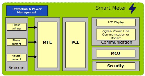
Figure 1: System synoptics of Energy Metering application circuit
Table 1 shows an example of differences in terms of performances and feature requirements for electricity billing meters and for smart outlets (monitoring in house electricity consumption). Depending on targeted applications and for achieving the best RoI, the system integrator must finally take care of needed performances, sensor performances, required computation and features.
| Billing meter | Home appliance (smart outlet,...) | |
| Class | 0.1 to 2 | 0.5 to 2 |
| Range | 500 to 5000 | 500 to 3000 |
| Active power/energy | Mandatory | Mandatory |
| Reactive power/energy | Optional | Optional |
| Apparent power/energy | Optional | No |
| Anti-Tampering function | Optional | No |
| Standard to comply | Yes (IEC or ANSI) | No |
Table 1: Comparative table of required functions for each application type
The meter performances are defined by its class and range. The class refers to the energy measurement accuracy and the range refers to the input current range for which the accuracy is achieved. For example, a power meter of class 0.1 with the range 1000:1 means the meter (specified for active or reactive power) measures this energy with less than 0.1 % error over a current variation from 1 to 1000 (maximum current shall be specified).
Today in the market, classes from 0.1 to 2 % and ranges from 500 to 3000 or greater are commonly available. Other than class and range, standards require a lot of tests (power factor, line frequency, temperature variation and immunity to interferences, ESD) that must be passed for claiming standard compliance. It is to bear in mind that higher measurement accuracy drives significantly future high-end smart metering market demand in billing meters.
In order to achieve high system performance, the measurement sub-system including the sensors and application schematics (ASC), the MFE, with its power management and the PCE shall be considered. It is important to be able to understand the potential errors of each part in order to be able to minimize their effects (by calibration or design) since a change of any of these parts can potentially influence system performances and cost.
Error contributions in a metering subsystem
During the meter specification phase, the total error budget has to be considered for the whole subsystem and cannot be allocated only to the MFE+PCE. Indeed, sensor and application schematics errors are also part of the error sources. Assuming a Gaussian error distribution for each error source, the total meter error will be equal to:
![]()
Using this formula, some compromises are presented in Table 2 for various classes:

Table 2: Meter error distribution between sensor and AFE for various classes
To be able to perform such trade-offs between sensor and MFE+PCE errors, it is essential to understand how each part works and the potential impact of its errors on performances. The goal is to be able to make the best error budget trade-off according to specific constraints of each part.
Sensors used for current measurement
The sensor is the first element in the chain, which must be chosen appropriately according to final application requirements, including target cost and performances. Table 3 lists the comparative matrix of the 3 principal sensors used for current measurement in electric meters.
| Current Transformer | Shunt Resistance | Rogowski Coil | |
| Cost | High | Lowest | Low |
| Range linearity | Medium | High | High |
| Power consumption | Low | High | Low |
| Temperature drift | Low | Medium | Low |
Table 3: Comparison of current sensors used in electric meters
Description of Energy Measurement Front-End
The energy measurement front-end is composed of the MFE, PCE and power management part, as shown in Figure 2.
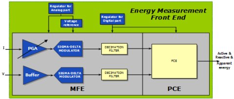
Figure 2: Description of the Analog Front End Measurement of an Energy Meter IC
Below is the short description of each major part of an energy measurement front-end:
- The MFE (Mixed signal Front-End), which contains a PGA (Programmable Gain Amplifier) in order to handle various sensor types and a high resolution ADC (Sigma-Delta modulator and decimation filter), allows converting the analog signal to a digital signal.
- The PCE, which is a pure logic block, performs the power computations on digital signals (I and V) provided by the ADC. The needed power computation figures depend on system application requirements.
- The power management part supplies all the necessary voltages to MFE and PCE. It consists in a low noise regulator dedicated to the analog part, a regulator dedicated to the digital part and very low drift reference voltage dedicated to the ADCs.
Error contributions of sensor and energy measurement front-end: their impact and the way to compensate them
Table 4 lists the main error contributions in a metering system for the sensor and MFE+PCE, as well as their impact depending on the targeted class.
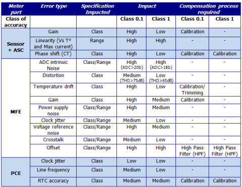
Table 4: Main error contributions in a metering system with its associated impact for class 0.1 and 1
Impact of most of these errors is relatively low or can be significantly reduced thanks to an accurate calibration process. Figure 3 presents the different required calibration stages to be handled by the MFE and PCE.
Temperature drift, phase shift and gain can be calibrated. Offset can also be calibrated but is usually only used for DC current measurement.

Figure 3: Calibration features embedded in the Analog Front end for smart meters
As listed in Table 4, the error sources, which have a high impact on system performances and that cannot be calibrated, are the intrinsic ADC, voltage reference, analog regulator noise and the clock jitter. These noises will appear at the output of the MFE as a quadratic sum with the ADC intrinsic noise:
![]()
After analyzing the error sources from sensors and MFE, it is time to investigate the Power Computation Engine (PCE), as it links the noise output from MFE to the class and range standard requirement. Indeed, the 3 error types from PCE described in Table 4 have low or medium impact on the system performances and they can be significantly reduced by the design of the PCE itself.
It is then compelling to see how the PCE can cope with MFE to lower the overall silicon area and reduce the errors due to MFE, while achieving a target system standard.
Power/energy computation
The active power, P, can be expressed as follows: P=Vrms.Irms.cos φ, with φ the phase difference between the instantaneous values of voltage and current. To compute the active power, the PCE processing chain is composed of two computation steps, as illustrated in Figure 4. First, the instantaneous power is obtained with a direct multiplication between the voltage and the current channels. Then, the active power, which is represented only by the DC component, is extracted from the instantaneous power with a low pass filter. At the output of the multiplication, the 2ω (100 Hz) component due to instantaneous power computation, which needs to be rejected more than 60 dB to be negligible, requires to correctly specify the low pass filter.
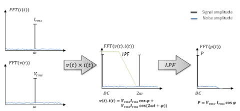
Figure 4 : Active power computation steps
As shown in Table 4, two sources of errors remain which may affect the meter class range performances. The first one is offset which is removed by the embedded High Pass Filter (HPF) on the MFE. The other one is the MFE noise, which constitutes the main measurement error contributor.
In the active energy measurement, the MFE noise present at the voltage and current channel outputs is directly summed to the power signal measurement. The meter is thus even more sensitive to the MFE noise if the current signal level is low. Although it can be attenuated thanks to a Low Pass Filter (LPF), it cannot be totally removed.
In addition, the conversion of power into energy is done by time accumulation of the power measurement. This accumulation will act as a supplementary low pass filtering stage, which further decreases the impact of MFE output noise. As shown in Figure 5, the higher the accumulation time is, the higher the meter performances are.
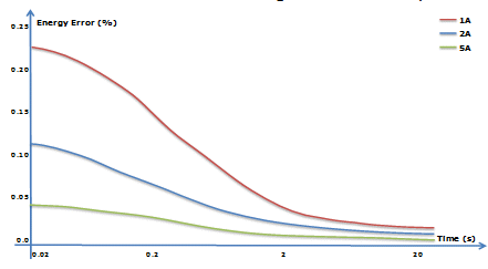
Figure 5 : Impact of accumulation time/pulse meter constant on active energy error for different current levels
The mastery of the measurement chain thus allows to understand the different relationships between the errors introduced by the various analog stages and the achievable performance for power measurement. However, the choice of processing architecture does not remain simple, and the best trade-off between the performance and the processing cost (essentially the silicon area) must be retained. As illustration, Figure 6 presents the range achievable for two different MFE, one having a 20-bit resolution ADC and the other a 21-bit ADC, when varying the processing complexity to improve performances and, thus, the PCE silicon area.

Figure 6 : Trade-off illustration between product surface and achievable Range for a class 0.1 and for a CT.
This figure shows that the best trade off using an MFE with a 20-bit ADC or with a 21-bit ADC is respectively achieved for a range equal to 5000 and 7000. This also shows that improving the PCE does not continuously lead to improved performances: ADC noise is the main factor limiting achievable range performances when targeting high ranges. In conclusion, the main objective of the designer results in defining the optimum point for achieving highest performances, while maintaining a reasonable silicon area.
A unique transfer of know-how for ensuring safe integration
As described in Table 3, for achieving a high accuracy class 0.1, the power supply noise and reference voltage noise have high impact on system performances. Without proper specification of how the measurement IP or IC solution can tolerate supply noise and clock jitter, the integrator cannot verify whether the final performances at system level will be reached. For enabling its customers to perform early performance assessments, Dolphin Integration provides a complete power metering offering, JADE, including:
- Solution achieving a class 0.1 % (0.07 % at SoC level) up to range 5000:1 with a shunt resistor,
- Measurement MFE with 20-bit or 21-bit delta-sigma ADC,
- Embedded PCE for active, reactive and apparent energy, with best trade-off between MFE and PCE for optimized silicon area and BoM cost,
- Features such as anti-tampering, voltage sag, peak detection, over-voltage/current detection, in-die temperature sensing,
- Embedded power management and low drift voltage reference to reduce the system noise disturbances, together with Power Supply Tolerance Templates (PSNT2) allowing the integrator to correctly choose the external regulator,
- Simulation models or advanced views for verifying system performances per power supply, voltage reference noises and clock jitters, prior to SoC tape out and/or PCB fabrication,
- Detailed calibration procedure,
- Simulation techniques know-how transfer with powerful multi-level and multi-domain EDA solution.
Summary
With the rapid growth of worldwide demand for smart electric meters, for new installations or for replacing old ones, the availability of a high-performance and high-quality measurement analog IP is pivotal to help Fabless makers enter such a performance competitive market.
Time-To-Market requirements, and the need to ensure a cost-effective IC, make it vital to comply right-on-first-pass with the targeted Class and Range power meter standard. As the meter performance depends on the performance of each component of the subsystem, it imposes a wise selection of the Mixed Signal Front-End and of the PCE as emphasized through this article.
This article demonstrates that only a top-down specification – from system specification to Silicon IP specification – may provide the insurance to achieve the performances targeted at the power meter level. It also helps understand the importance of considering the energy metering constraints as standard test compliance, calibration requirements and the need to support various kinds of sensors.
As a result SoC designers in charge of the selection of the Silicon IP may identify whether the providers have specified optimally their Silicon IP to achieve the best trade-off between performances and silicon area as targeted by Dolphin with its Metro-PM-Jade-Mono.05 or Metro-PM-Jade-Mono.15 Silicon IP products. A flexible offering, such as that of Dolphin Integration, for configurable MFE and PCE, ensures an optimal silicon area for each application requirement (home appliances or billing meters).
Finally, the availability of the appropriate simulation models for the Silicon IP provides the SoC Integrators with the capability to safely tape-out their SoC. The know-how for mastering such simulation techniques has been “productized” by Dolphin to facilitate its transfer whenever needed.
Explore Dolphin Integration IP here
- Complete measurement subsystem IP for single phase power metering
- 20 bits Analog Front-End optimized for Low Area & Low BoM for High resolution applications
About the authors
Christian Domingues began his semiconductor career at the Techniques of Informatics and Microelectronics for Integrated Systems Architecture (TIMA) laboratory. Since 2006, he has been involved in Dolphin integration as a mixed signal design architect, working in the field of high-performance measurement ΣΔ ADCs. He received a master’s degree and a PhD from the Polytechnical National Institute of Grenoble (INPG) in France in 2001 and 2005, respectively. Mr. Domingues can be reached at cdo.jazz@dolphin.fr
Lionel Pierrefeu received his PhD degree in Micro-electronics, image and signal processing in 2009 at the University of Saint Etienne. From 2009 to 2010, he worked at the GIPSA labs (Grenoble) as Post doctorate on the design of micro-electronic architectures for image and signal processing. Since 2011 he has integrated Dolphin Integration as digital design engineer, working on signal processing architectures dedicated to audio and metrology subsystems. He has been recently involved as digital signal design architect for the Power metering subsystem.
Hugo KUO is Dolphin's FAE in mixed-signal high-resolution converter subsystem since January 2006. He co-authored several publications for launching Dolphin's worldwide strategy of Application Hardware Modeling (AHM) since 2009. He received a microelectronic engineering master degree from Grenoble Institute of Technology (INPG) in France in 2005, with one year exchange program at EPFL (The Swiss Federal Institute of Technology Lausanne) in Switzerland. Mr. Kuo can be reached at fae.asia@dolphin.fr
Related Semiconductor IP
- xSPI Multiple Bus Memory Controller
- MIPI CSI-2 IP
- PCIe Gen 7 Verification IP
- WIFI 2.4G/5G Low Power Wakeup Radio IP
- Radar IP
Related White Papers
- Leverage always-on voice trigger IP to reach ultra-low power consumption in voice-controlled devices
- New Power Management IP Solution Can Dramatically Increase SoC Energy Efficiency
- Multiplexed Energy Metering AFEs Ease ASIC Integration and Provide Significant Cost Reduction
- Silicon Qualified SuperViC: the only way to safe SoC integration