Introduction to Low Dropout (LDO) Linear Voltage Regulators
By Anand Veeravalli and Stephen M. Nolan (Vidatronic)
ABSTRACT
Linear voltage regulators are key components in any power-management system that requires a stable and ripple-free power supply. A subset of linear voltage regulators is a class of circuits known as low dropout (LDO) regulators. This paper explains the fundamentals of LDOs and introduces Vidatronic’s LDO technology which solves many of the known shortcomings of LDO circuits. LDOs are available as both stand-alone packaged devices and as intellectual property (IP) cores that can be integrated into a larger integrated circuit design. This paper deals with the fundamental principles of this class of circuits and, therefore, is applicable to both stand-alone devices and IP cores. There are several articles available regarding LDOs. While some of them are highly technical and heavy on mathematical analysis, others are generic and don't go into any detail. This paper attempts to strike the right balance to appeal to a wider audience. Several basic aspects of these circuits are discussed, with the intention of giving the reader a simple overview, rather than delving into complicated details and mathematical derivations. The motivation for this paper is to make the readers comfortable with the topic of LDOs and to prepare them for assimilating more advanced topics. Key electrical specifications are examined and contrasted against Vidatronic’s IP cores towards the end of the article, to showcase the differentiation provided by Vidatronic.
Learn more at vidatronic.com.
INTRODUCTION & BACKGROUND
A linear voltage regulator is a circuit that takes in a variable input voltage and provides a continuously controlled, steady, low-noise DC output voltage. Generally, linear voltage regulators require a large voltage drop between the input and the output to function correctly. This requires a relatively high-voltage input power supply and results in low power efficiency. A low dropout (LDO) linear voltage regulator is a type of linear voltage regulator circuit that works well even when the output voltage is very close to the input voltage, improving its power efficiency.
LDOs have two main functions, the first obviously being the reduction of an incoming supply voltage to the lower voltage that is needed by the load. A second function is the supply of a very low-noise voltage source, even in the presence of noise on the incoming power supply or transients in the load. In fact, this is their main advantage over switching converters, where noise isolation and emissions are major system concerns.
FUNDAMENTALS OF CIRCUIT OPERATION
The fundamental concept of the linear voltage regulator is shown in Figure 1.
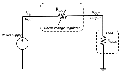
Figure 1: Linear Voltage Regulator Fundamental Concept
In simple terms, the linear voltage regulator is an effective impedance (RLDO) that is presented to the load (RLOAD) so that the excess voltage is dropped across RLDO in order to maintain the required voltage levels at the load.
In many systems, the power supply providing the input voltage varies considerably, which, in the above implementation, would cause the output voltage to also vary by a corresponding amount. For this reason, it is necessary to add a closed-loop control system to ensure the output voltage remains constant, independent of the input line voltage. Such closed-loop feedback networks usually regulate by using a fixed voltage reference, typically provided by a bandgap reference circuit. Figure 2 depicts the closed-loop system.
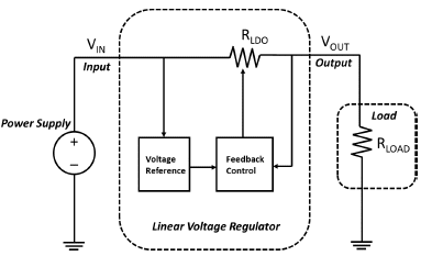
Figure 2: Simplified Linear Voltage Regulator
The linear voltage regulator output voltage (VOUT) is now independent of the input source voltage (VIN) and is directly related to the voltage reference. If this voltage reference is stable and clean, the output is generally immune to any line changes. If the control loop is fast enough, then the regulator can also maintain a steady output voltage during abrupt transient changes in load current.
When the design of the regulator is such that the minimum required voltage drop across RLDO is small (a few hundred millivolts or less), then this is known as a low dropout linear voltage regulator or simply LDO.
ADDITIONAL FEATURES
In addition to the above-mentioned fundamental functionality of an LDO, several other useful features can be included.
Enable/Disable
Many LDOs have a control input to enable the regulator or shut it down. This is useful for overall system power savings where the regulator is turned off when the system is idling or in an inactive state. There can be more intermediate power states, such as low power mode or ultra-low power mode, where the LDO output is maintained at the cost of system performance, depending on system requirements.
On devices with active-high logic, a high logic level enables the regulator, while a low input disables it. Vidatronic’s LDO IP cores use this convention.
Soft-Start, Soft-Shutdown
Powering up the LDO is an important event and care must be taken to ensure that the output voltage rises at the optimal speed. If the voltage builds up too fast, it can trigger ESD clamps at the output and/or drive more than the rated current while trying to charge up the load. To prevent such unwanted occurrences, which can cause temporary or permanent damage to circuitry, the rate at which the output comes up is controlled. This is called Soft-Start.
Vidatronic’s IP cores provide Soft-Start functionality, ensuring a smooth, monotonic startup. The maximum slew rate is internally limited and given in the electrical specifications table of the datasheet.
Similarly, when the LDO is disabled, the output voltage will decay as a function of output capacitance and load current. Vidatronic’s IP cores have an additional feature normally not found on most LDOs. Should the part be re-enabled before the output fully decays, a slew rate function within the IP core will first bring the output voltage to zero before restarting, thus eliminating issues with startup glitches or non-monotonicity.
Over-Current/Over-Temperature Shutdown
In the event of prolonged exposure to conditions over and beyond the rated temperatures and load current levels, immediate or long-term damage to the device can occur. To safeguard against these risks, power systems usually have built-in over-current and over-temperature protection circuitry. There are different implementations that can be found from different manufacturers. Some are simple analog circuits that shut down the device when set thresholds are reached and require the faulty conditions to be removed before they can power up again. More advanced implementations include periodic polling to check if the faults are present or removed. In the case of persistent faults, this polling continues indefinitely.
For Vidatronic’s IP cores, in the case of an over-current, the device will set a flag and initiate a Soft-Shutdown. After the current is decreased to zero, the part will wait a turn-on delay time of some milliseconds and then proceed with a slew-rate-controlled startup. This operation will continue indefinitely until the fault disappears.
In the case of an over-temperature condition, once the temperature of the device reaches the over-temperature rising threshold, the LDO will shut down using the Soft- Shutdown procedure. Once the device temperature falls below the falling threshold, the device will again restart after waiting for some milliseconds. The flags are not reset until the device is disabled and then re-enabled.
Undervoltage Detection and Overvoltage Detection
Input voltages can undergo sudden excursions that can have catastrophic consequences if they are outside acceptable values. An undervoltage (sometimes called a “brownout”) condition can force the LDO output to go below its regulation window, causing the load to fail functionally. An overvoltage is cause for reliability or Safe Operating Area (SOA) concerns.
Detecting the occurrence of these abnormal conditions is useful for designing failsafe limits in the overall system. Depending on the application space, many LDO manufacturers offer one or both voltage excursion detection features. One of the common responses to such faulty conditions is shutting down the regulator and flagging the system.
The circuit that responds to the undervoltage or brownout condition is typically called an undervoltage lockout, or UVLO. Should the input voltage fall below the required threshold to maintain regulation for Vidatronic’s IP cores, the regulator will set an internal flag and proceed with a Soft-Shutdown. A power-on-reset must be initiated for the device to initiate a Soft-Startup.
Should the input voltage exceed acceptable limits, a warning flag from the LDO would alert the system’s supervisor to take appropriate corrective actions to remove the source conditions responsible for causing these faults. For example, by shutting down the main power source to the LDO.
DC ELECTRICAL CHARACTERISTICS
There are multiple DC electrical characteristics of LDOs that should be carefully considered during their selection including: input voltage range, dropout voltage, quiescent and shutdown currents, minimum “bleeder” load, and regulation accuracy.
Input Voltage Range
This is the range of allowable voltages at the power supply input to the LDO. Wider input voltage ranges allow a device to be used where the supply varies greatly, such as battery-powered applications.
Dropout Voltage
Dropout voltage is another important parameter for an LDO, as the name suggests. This is a measure of the minimum allowed difference between the line input and the output voltages the LDO provides while driving the full-rated current. The smaller this number, the higher the power efficiency of the system. Most LDOs range from 70 mV up to 500 mV for higher performance designs, which require larger voltage headroom for achieving improved performance metrics.
This is one of the parameters that could impact the circuit architecture that is chosen for the output power delivering stage. Smaller dropout voltages often mean a p-type output pass element, which is inherently larger in size than the corresponding n-type stage for a given load current.
Vidatronic’s Noise Quencher® IP cores offer dropout voltages as low as 40 mV at 100 mA by using a charge-pump architecture, thus enabling the highest possible output voltage levels at very low supply voltages.
Quiescent Current
System power efficiency as well as battery life is greatly impacted by the quiescent current, IQ, and the shutdown, or leakage current, ISD. Larger IQ in the range of several hundreds of μA or a few mA is typically required to achieve high AC performance metrics. Further, these usually scale with load current, becoming larger when the LDO is delivering full power.
Vidatronic’s IP cores are designed to keep these values to less than 100 μA at full load, making them an ideal choice for high-performance and low-noise batteryoperated applications. Vidatronic’s shutdown currents are less than 20 nA, even at the maximum junction temperature allowed.
Minimum “Bleeder” Load
Typically, LDOs require a minimum “bleeder” load current at the output to remain stable. This is to keep the output power device from saturating the loop internally.
Vidatronic’s Noise Quencher® Technology removes the need for a minimum load to guarantee stability. The LDO will remain stable for all load conditions up to the maximum-rated current. This feature is useful in extending battery life for battery applications and in CMOS RAM keep-alive applications. Further, good stability at zero load current enables the system to continue to operate for disabled loads, thus removing latency and delays in the system.
Output Accuracy and Load Regulation
Output voltage accuracy measures the regulation accuracy of the feedback loop and load regulation indicates the drive capability of the regulator in handling load current changes.
Most LDOs offer accuracies in the range of a few percent and load regulation in the range of 10-50 mV/A. In contrast, Vidatronic’s LDOs offer an industry leading load regulation of < 2 mV/A. This, coupled with outstanding dynamic performance as well as best-in-class output accuracy of 1%, makes Vidatronic’s IP cores perfect for applications requiring high levels of precision in output voltage control.
THERMAL CONSIDERATIONS
Thermal considerations are paramount in any power system, as they have the potential to cause irreversible damage to the device if the maximum allowable junction temperature is exceeded. Over-temperature protection circuits are typically included in systems that deal with moderate to high power levels. For example, one of Vidatronic’s IP cores is designed to provide 300 mA continuous current.
The maximum ambient operating temperature will be based on the load current and the voltage drop across the device. Equation 1 is used to calculate the maximum power dissipation of the device based on the load conditions. The maximum junction temperature is then found using Equation 2, where TAMB is the maximum ambient temperature and ƟjAMB, is the thermal resistance of the junction to ambient and is determined by the specific package chosen.
Equation 1
![]()
Equation 2
![]()
IQ above is the quiescent current consumed by the LDO. Equation 3 can then be used to calculate the maximum junction temperature for a given thermal impedance of the junction to the board.
Equation 3
![]()
These calculations are usually key to ensuring the system can deliver maximum power, without causing thermal issues. Selecting the right package is very important in this context. Some packages have a heat sink built into them to help lower the thermal impedance significantly, sometimes by as much as 30% to 40%. Such packages, however, typically cost more and are bigger in size, and a careful thermal modeling/simulation is recommended to ensure the optimal package is chosen for the application on hand.
AC SPECIFICATIONS
Transient Line Response
The output voltage of high performance LDOs is mostly independent of the input line voltage and is expected to remain so, for both DC and instantaneous variations on the line. Due to practical limitations, such as finite loop gain and finite loop bandwidth, as well as parasitic leakage paths from the input to the output, the output voltage will have a component that is dependent on the input line, albeit attenuated in magnitude and shifted in phase. The DC component is usually measured in mV/V, while the AC component is shown as an attenuation in decibels (dB).
Transient Load Response
The LDO output is ideally independent of the load current as well. However, due to the finite closed-loop output impedance of the regulator, the output voltage will vary a little bit due to load changes. The DC component is just the load line measured at the output, while the transient part is a function of the output capacitance present at the load point and the closedloop bandwidth of the amplifier, as well as the rate at which the load current is changed. Typically, this is measured in mV/A, with the load changing from the minimum to the maximum as a step function. There will also be a strong dependence on how the input line is supplied to the regulator, with the input Power Delivery Network (PDN) inductance and decoupling playing a key role in the regulator output. Care must be taken to ensure that any package resonance is kept well outside the frequency band of interest.
Output Noise
The integrated output noise of the regulator is usually determined by the noise of the reference input, the closed-loop gain of the regulator, and the noise of the input stage of the error amplifier. While the reference noise can be band-limited by placing an appropriate filter function before the regulator, the amplifier’s input stage noise will be amplified by the closed-loop gain and it will appear at the output. Depending on the type of components and the architecture used in the input stage, the main noise components will be shot noise, flicker noise and/or thermal noise. These need to be budgeted and designed to a given noise specification.
Power Supply Rejection Ratio (Line Regulation)
Power supply rejection ratio (PSRR) is a key parameter in LDO design and is often used to compare competitive devices. Essentially, PSRR is a measure of how much the output voltage moves for a given perturbation on the input. Ideally, the output should be independent of the input, but due to practical limitations, this will not be the case and some amount of this disturbance will “leak through” to the output. A 20 dB rejection means a 10X attenuation of the line noise to what is seen at the output. For most LDOs, this falls off rapidly with higher frequencies because of the characteristics of the control loop. At frequencies of 10 MHz or more, most LDOs will have almost zero rejection or at best a few dB.
The Vidatronic’s core cap-less architecture provides the end user with the most aggressive PSRR available, as it can achieve 40 dB at frequencies up to 10 MHz. This improved attenuation further reduces the need for the small high-frequency decoupling capacitors that are typically used in noise sensitive applications, and makes Vidatronic’s IP core a perfect choice for these applications.
LOOP COMPENSATION
As with any closed-loop control system, the LDO feedback loop needs to be frequency compensated for the output voltage to be stable. A careful analysis of the various poles and zeros of the loop filter is required, and this analysis is typically the most complex part of the design of an LDO, requiring a significant amount of design time.
Previous Solutions
One of the common approaches to frequency compensation of LDO loops is to use a very large capacitor at the LDO output. Such LDOs are called output-compensated regulators. The exact capacitor values depend on several factors such as load current, headroom available, and others. Typical values are in the range of hundreds of nF to a few μF. These capacitors help with sourcing or sinking surge currents due to fast load changes. The main drawbacks with such systems are the additional cost for these external capacitors and the extra space on the PCB for mounting them. Typical Internet of Things (IoT) systems and other similar applications require several LDOs. A capacitor for each LDO output will very quickly become prohibitive.
Another factor is that the range of required values for the load capacitors usually spans a few decades or more, depending on the circuit. It is impractical to design custom LDO cores that work for every application, even though it is often desirable to re-use an existing core for different applications. Working out a frequency compensation scheme that can support such a wide range of output capacitors is an extremely tough requirement to meet. Conventional solutions to such problems result in over-design in terms of silicon area and additional circuitry, which invariably get passed on to the end user as additional cost and size.
Vidatronic’s Solution
Vidatronic has a unique solution for such problems. Vidatronic’s LDOs use a novel load-detection scheme that allows the LDO to sense the amount of capacitive load the regulator sees at the output and automatically configure itself to the most stable internal compensation scheme. This “calibration” is done one time, at startup and then is done. The advantage of this is two-fold:
- Vidatronic’s LDOs do NOT require an external capacitor to be stable! Vidatronic’s patented Noise Quencher® technology ensures good transient response even for fast load transients, WITHOUT the need for an external capacitor.
- Vidatronic’s LDOs will AUTOMATICALLY adjust internal compensation to be stable if the customer decides to place an external capacitor for specific performance reasons (for instance to achieve very high noise suppression).
VIDATRONIC TECHNOLOGY
Functional Characteristics
Vidatronic’s Noise Quencher® LDO is a low quiescent current, low dropout linear voltage regulator IP core that can provide up to 1 A of continuous output current. Using Vidatronic’s Noise Quencher® Technology, the regulator is able to support very high load transients with very small output excursions while providing excellent PSRR, even at high frequencies, all without requiring an external output capacitor. A simple block diagram is shown below in Figure 3.
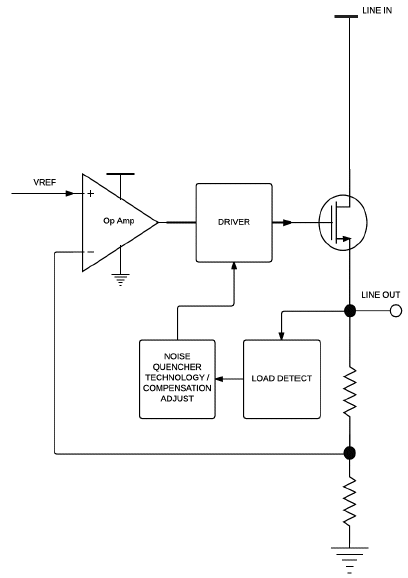
Figure 3: Simplified Block Diagram of Vidatronic’s Noise Quencher® IP
Output Capacitor - Dynamic Performance
Vidatronic’s capacitor-less LDO regulator IP core is optimized to provide best-in-class transient performance in both analog and digital applications without the use of output capacitance. Using Vidatronic’s Noise Quencher® Technology, Vidatronic’s designs are able to support load transients up to 150 mA/μs with less than a 45 mV output-voltage excursion without external output capacitors. This patented technology provides the opportunity to reduce the total solution board area by approximately 25%, making this solution optimum for smartphones and other applications where board area is a premium, like wearable electronics and IoT applications. For increasingly demanding applications, Vidatronic’s designs can support output capacitors up to 10 μF and still be unconditionally stable.
For optimum stability of the LDO, Vidatronic uses a proprietary patented technology in Vidatronic’s Noise Quencher® designs that detects the capacitance presented at the LDO output at startup and automatically configures the internal compensation circuitry to be at the optimal setting. Using this technology, Vidatronic’s LDO IP cores offer unconditional stability across output load capacitors from 0 to 10 μF, a range that spans over several decades. This feature gives maximum flexibility to the end customer, depending on the application space, allowing the same IP core to be effectively used across multiple designs.
APPLICATION CONSIDERATIONS
LDOs are used in a wide range of power management applications across many fields. They are usually lowcost, small-sized, and produce a stable and relatively ripple-free output-voltage supply to provide power to application circuits.
LDOs are frequently used in conjunction with application specific integrated circuits (ASICs) and Systems on a Chip (SoCs), which require multiple clean, low-voltage supplies.
Vidatronic’s LDO IP cores are targeted toward ASIC and SoC integration for both micro-powered applications such as Internet of Things (IoT) products and battery-powered applications such as mobile and portable devices. The Vidatronic IP portfolio is also expanding to provide higher-voltage, higher-current capabilities used in wall-powered applications, such as industrial systems.
Output Capacitor Considerations
Typically, many LDOs require a large external capacitor to be placed near the LDO output for several reasons such as loop stability, transient response improvement, and lowering the noise bandwidth. The value of this capacitor ranges between a few nF to a few μF, sometimes even more. If placed for loop stability reasons, the equivalent series resistance (ESR) of this capacitor is very important as it can impact the loop stability if it is too high.
The type of capacitor is another key consideration. While electrolytic capacitors tend to give larger capacitance values, they are also bigger and their dielectric performance is poorer. Ceramic capacitors are recommended for LDO applications over electrolytic capacitors, with X5R or X7R dielectrics preferable due to their superior thermal and DC bias performance, compared to Y5V and Z5U dielectrics. Yet another consideration would be the foot print size such as 0201, 0402, 0603, etc. and this needs to be chosen based on board space available and electrical properties of the resulting capacitor choices.
Packaging
It is worth mentioning here that the choice of package (such as CSP or QFP etc.) is another important aspect, as this ends up limiting the ultimate performance of the regulator due to parasitic RLC elements present in the package. A detailed package electrical and thermal model is a must for a successful design, as these effects must be rolled into the design process to avoid unpleasant surprises later on. Packaging and thermal considerations are detailed more in the later sections of this article, to impress upon the reader their importance.
LDOs come in different types of packages such as SOT, QFP/QFP, USP (ultra-small package), and CSP (chip scale package). There are different tradeoffs associated with the packages in terms of electrical performance, thermal performance, size, and cost. For example, CSP packages have the least amount of parasitic resistance and routing inductance to the PCB, but their thermal performance is not as good when compared to standard wire bond packages. Further, they come in several pitch options such as 0.5 mm to even 0.3 mm these days. While the small pitch does help to reduce the solution size significantly, they also require more complicated assembly flows to mount them on the PCBs. It is recommended to do a thorough study of these factors before choosing the final package.
Electrostatic Discharge (ESD)
Primary and secondary protection structures may be required on the LDO output and other circuitry, depending on the device sizes and internal architecture. Care must be taken to ensure that the electrical I-V curves of these structures and their trigger mechanisms are in sync with the transients that can be expected on these pins during device operations such as power up, turn OFF, and other such dynamic events. Typical requirements are 2K V human body model (HBM), while specific applications might require much higher protection levels, as in the International Electro-technical Commission IEC 61000-4 series specifications.
LDO Simulation Analysis
Careful simulation analysis is often required to ensure a successful product. In addition to some of the usual functional and performance simulations that are run and documented in a detailed Spec Compliance Matrix (SCM), it is recommended to pay special attention to end-usage scenarios that could potentially break the operation of the LDO. It is useful to make a list of all of the system-level considerations in order to understand what could go wrong. Building margins and identifying risk mitigation methods goes a long way in improving production yields. Some of the critical performance simulations include PSRR and transient load regulation, as these depend on multiple AC effects that can occur due to parasitic elements. Figure 4 shows a typical PSRR waveform for Vidatronic’s LDO IP cores, whereas Figures 5 and 6 show measured line and load transient response respectively.
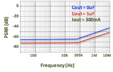
Figure 4: PSRR vs Frequency without any Output Capacitor
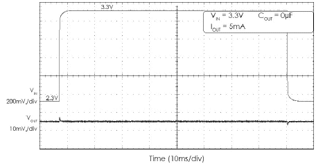
Figure 5: Line Transient without any Output Capacitor
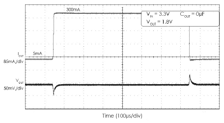
Figure 6: Load Transient without any Output Capacitor
As can be seen from the figures above, the transient line regulation is only a few mV for a 1 V step in the line input. Also, the line regulation or PSRR is 40 dB, even at frequencies as high as 10 MHz, without any external capacitor. The load transient excursions are bounded to within 40 mV for a full load step. Most of the competitive devices require a large output capacitor in the μF range to achieve similar performance metrics.
SELECTING THE RIGHT LDO
We have thus far seen several parameters that define LDO performance; however, different applications place greater emphasis on some specifications over others. For example, IoT/mobile applications prioritize quiescent and shutdown current, as these are battery-powered and see extended idle/shutdown periods during system operation.
Other applications, like powering RF circuitry such as VCOs, mixers, and PLLs, require very low noise in the frequency bands of interest and low PSRR at higher frequencies, as these translate directly to channel jitter and intermodulation (IM) distortion.
Yet others that go on miniaturized devices, such as wearable devices, require a small area footprint as PCB space is premium in these applications.
LDOs that are used to power high-speed loads, such as cache memories and microprocessor cores, require very low transient droops in presence of large di/dt load switching and can accept a higher quiescent power. Other LDOs that are used to power high-speed digital loads require very tight voltage set-point accuracy for maximizing the frequency of operation while keeping the power as low as possible. The precision required is in the range of 10 mV across circuit variations for such applications.
Thus, there is no “one size fits all” in the matter of choosing the right LDO for the application under consideration. This topic is covered in another Vidatronic White Paper: “Guide to Choosing the Best LDO for Your Application.”
We leave the reader with a summary of electrical performance numbers for Vidatronic’s Noise Quencher® IP Core.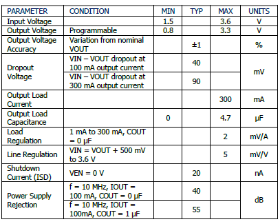
This is also an appropriate juncture to introduce Vidatronic’s Power Quencher™ IP Core, which attains extremely low quiescent power consumption in the regulator core while providing excellent analog performance. This is achievable without requiring external capacitors and is ideally suited for IoT applications, where low power consumption and solution size are both critical. A sample table below highlights the key features of this solution, to give readers a feel for the electrical performance metrics.
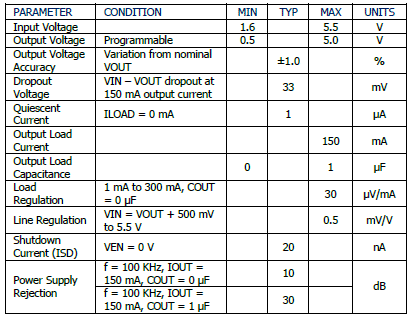
In summary, with the Noise Quencher® and the Power Quencher™ technologies, Vidatronic aims to give differentiated solutions that cover a wide application space across several end systems.
CONCLUSION / SUMMARY
This white paper is meant to introduce the reader to the basic concepts and technical parameters of a LDO. Basic operation, features of interest, and key electrical specifications used for comparing designs have been explained in simple terms, without resorting to complicated mathematical analysis. Against this background, Vidatronic’s LDO technologies have been introduced and showcased to highlight the unique differentiation these technologies bring to the market, which place Vidatronic’s LDO technologies on a level that is distinctly superior in performance.
REFERENCES
- https://www.torexsemi.com/technical-support/application-note/basic-knowledge-of-ldo/overview/
- http://electronicdesign.com/power/low-dropout-ldo-linear-regulators
- https://www.baldengineer.com/regulator-basics.html
GLOSSARY
- AC: Alternating Current
- ASIC: Application Specific Integrated Circuit
- CSP: Chip Scale Package
- DC: Direct Current
- ESD: Electrostatic Discharge
- ESR: Equivalent Series Resistance
- HBM: Human Body Model
- IEC: International Electro-Technical Commission
- IP: Intellectual Property
- IM: Intermodulation
- IoT: Internet of Things
- LDO: Low-Drop Out Linear Voltage Regulator
- PDN: Power Delivery Network
- PCB: Printed Circuit Board
- PSRR: Power Supply Rejection Ratio
- QFP: Quad Flat Package
- SCM: Spec Compliance Matrix
- SOA: Safe Operating Area
- SoC: System on a Chip
- USP: Ultra-small Package
- UVLO: Undervoltage lockout
www.vidatronic.com
Related Semiconductor IP
- LDO voltage regulator
- 50 mA LDO voltage regulator (output voltage 0.9V/1.2V/1.34V) on Samsung 65nm
- 50mA capacitor-less LDO voltage regulator (output voltage 0.5V to 0.8V)
- LDO Voltage Regulator, Adjustable 0.45 V to 0.9 V Output, 30 mA, TSMC N3P
- LDO Voltage Regulator, 250 mA, TSMC N3P
Related Articles
- The Tradeoffs of Low Dropout (LDO) Voltage Regulator Architectures and the Advantages of "Capless" LDOs
- Pairing Sensitive RF with Voltage Regulators for Noise-Free IoT Modules
- Low Voltage SRAM - The Missing Link
- How Low Can You Go? Pushing the Limits of Transistors - Deep Low Voltage Enablement of Embedded Memories and Logic Libraries to Achieve Extreme Low Power
Latest Articles
- Timing Fragility Aware Selective Hardening of RISCV Soft Processors on SRAM Based FPGAs
- Bio-RV: Low-Power Resource-Efficient RISC-V Processor for Biomedical Applications
- PermuteV: A Performant Side-channel-Resistant RISC-V Core Securing Edge AI Inference
- Making Strong Error-Correcting Codes Work Effectively for HBM in AI Inference
- Sensitivity-Aware Mixed-Precision Quantization for ReRAM-based Computing-in-Memory