Implementing Field-oriented Brushless Motor Control Using an ARM7 Processor
Abstract:
Three-phase brushless motors offer many benefits including economy, reliability and high efficiency, but also exhibit poor dynamic performance. By implementing proper control algorithms (such as field-oriented control) on an ARM7 processor-based MCU, three-phase brushless motors can be made as dynamically responsive as separately - excited DC motors. This enables 3-phase brushless motors to be used in high-end motor drives for automotive, robotics, and industrial frequency converters, as well as some appliance applications. The article will demonstrate how these control schemes can be implemented on ARM7 processor-based products with the appropriate peripherals needed for state-of-the-art PWM generation and signal conditioning, avoiding the necessary learning phases associated with dedicated DSP or hybrid processor architectures.
When speaking about motor control, it is worth to reviewing some figures before entering the technical details. First of all, even if it is hard to believe, the number of electric motor produced per year is getting close to 10 billion. Brushless motors are accounting for around 10% volume in households alone, and are said to be multiplied several fold within the next coming years for domestic applications in particular. Last but not least, motors are responsible for a large part of the total electrical energy consumption: in 1991, they represented 65% of the United States consumption. From this standpoint, it is easy to understand that any percent gained in motor drive efficiency will lead to substantial energy savings: this explains partly the growing interest in advanced motor control algorithms.
Three-phase brushless motors, mainly AC induction (asynchronous) and permanent magnet synchronous, are known for their high efficiency, reliability, low maintenance, low cost and silent operation. The induction motor is already widely used for industrial applications such as pumps or fans, but it is now (as well as the PM synchronous motor) pervading other domains, such as home appliances, air conditioning, automotive or servo drives. This is driven by two main factors: 1) the price decrease of the electronic - they require an expensive power converter and, 2) the possibility to implement sophisticated control strategies overcoming their inherent poor dynamic performances.
As an example, let’s look at the asynchronous motor. To be simple, it requires three sine wave voltages, 120° degrees shifted, to be applied on the stator windings. These windings are arranged in such a way that a rotating flux is created. By transformer effect, this flux induces in the rotor cage a current, which in turns creates a rotor flux. The interaction of these two fluxes is the source of the electromagnetic torque that makes the motor spin. The condition to have a current induced in the rotor is to have the rotor speed different from the stator flux frequency: would the speed be the same, the rotor would just see a constant flux producing no current (Lenz law); this slight difference between the applied electrical and the resulting mechanical frequency is the reason of the asynchronous naming.
The simplest way to achieve variable speed operation for a three-phase AC motor is to implement a so-called voltage/frequency control (or scalar control), where the principle is to maintain a constant ratio between the frequency and the voltage applied to the motor. This produces a constant stator flux and the nominal motor torque is available on the rotor shaft. This is a very popular control method for low cost drives which are suitable for applications having well-known load characteristics and are not very demanding in terms of control bandwidth, i.e. few HP pumps and fans, washing machines, etc. A few MIPS 8-bit MCU with the appropriate peripheral set, such as ST7MC, fits perfectly and is very simple to be programmed.
Unfortunately, not all applications can afford such simple control and its limitations. Since it is based on steady state motor equations, it does not guarantee the optimum motor behavior (torque, efficiency) during transient operations. Furthermore, the drive reaction time has to be limited to avoid the motor to be temporarily demagnetized. To overcome these limitations, other control strategies have been developed, taking into account the dynamic characteristics of the motors.
The field–oriented (also called vector) control is the most widely used. It has been successfully industrialized in numerous general purpose industrial inverters for applications such as belt conveyors, large power pumps, air exhaust, factory automation... It allows driving an AC machine in the same way as a separately excited DC machine, with two decoupled control variables (here after mentioned as Id and Iq). The magnetizing current Ids corresponds to the DC main flux. Iqs controls torque just like the armature current does in the DC motor. Field-oriented control allows precise and responsive speed control when the load changes, and guarantees optimized efficiency even during transient operation by maintaining perfectly in quadrature the stator and rotor fluxes. It enables position control schemes (through instantaneous torque control) and provides full motor torque capability at low speed.
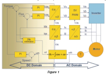
Here is in few words the principle of operations. The complex set of equations that describes an AC motor cannot be used directly. By changing reference coordinates from the fixed stator coil to the moving rotor flux frame, this set of equations is drastically simplified. This is achieved thanks to two well-known transformations. The Clarke transform converts the 3- axis 120° shifted coordinates (Ia, Ib, Ic) into 2-axis orthogonal ones (Ia, Ib); the park transform converts the fixed (Ia, Ib) coordinates into 2-axis rotating coordinates (Id, Iq) linked to the rotor. These two last variables are DC or slowly varying values which can be regulated by mean of simple PI controller. They are then finally transformed back to the fixed AC 3-phase frame (the stator windings) using the backward transforms (reverse Park & Clarke), as summarized on Figure 1.

Among the various vector control schemes, we have implemented an indirect rotor field-orientation where the only motor model parameter to be measured and handled is the rotor time constant Lr/Rr (in the slip estimator block). Would the motor be a Permanent magnet Synchronous motor, the block diagram and corresponding functions would have been very similar. The slip estimator is no more necessary and the flux command can be set to zero (the magnets are producing the flux by their own). This is another interest of vector control algorithms, for development teams having to deal with various applications and motor types.
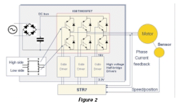
Algorithms are just one (big) part of the job: once the voltage levels are computed, they have to be converted into volts and amperes. As in almost any modern power electronics system, one can distinguish the brain: the MCU from the muscles: the power converter. This last (frequently called inverter) is driven by three pairs of PWM outputs (see Figure 2). It can simply be seen a triple powerful buffer, which translates a 0-5V logic signal into a 0-300V square wave applied to the motor terminals. The winding inductance of the motor acts as a low pass filter: it removes the carrier frequency and smoothes the current variations to have a sinusoidal current waveform which is the image of the PWM modulation.

Let’s now review the complete system requirements of an advanced motor drive one by one, starting with the CPU. The complete vector control algorithm must be continuously recomputed, at a rate of between 1 and 10 kHz (1ms down to 100ìs loop time, depending on the final application bandwidth). It intensively requires math computations (trigonometric functions, PID regulator, real-time flux and torque estimation based on motor parameters). Additionally, some room must be left to the rest of the application (communication, user interface, etc.). In order not to restrain dynamic performance possibilities, 16-bit is the minimum required accuracy for the main control variables, with a need for 32-bit calculations for intermediate results. All these factors explain why fast and powerful processors are mandatory for vector control: the market offer consists of 16- or 32-bit MCUs, hybrid controllers or DSPs. These last are by the way usually directly associated with advanced motor control, but we’ll see here below that unless you’re seeking for the fastest digital current control loops or the tightest trajectory controls, a standard ARM7 processorbased solution will do the flux orientation just fine.
Apart from core performance, it is also mandatory to have the right peripheral set to minimize the need for external components. This significantly simplifies the design process, ensures cost-effectiveness and reliability (thanks to a simplified PCB design).
For the signal generation side, general purpose PWM channels are not suitable. Motor control dedicated PWM signals are mandatory: one need 3 synchronized complementary pairs with dead time insertion to avoid potential short-circuits on the half-bridges. For the sake of security, these 6 PWMs have to be disabled synchronously in case of power stage failure/fault (over-current, over temperature…). An emergency stop input is dedicated for this function. Just to mention features that are now also considered as the state of the art for motor control, high timer clock frequencies (typically >50MHz) and PWM carrier frequency triangular rather than saw tooth will help generating very accurate sine wave with an optimal acoustic noise vs. switching losses trade-off.
Analog signal acquisition is the other main duty of the MCU. Two classes of signals must be monitored for motor control: slowly varying signals such as the DC bus voltage (with ~100Hz ripple) or trimmers and high dynamic’s motor currents, ranging from few Hz to several hundred Hz with a ripple at the PWM rate (typically above 10kHz). Analog-to-Digital converters need thus to be fast (below 5ìs), to reduce unbalanced current measurement when sequentially sampling the motor phases, and decrease the time spend in the PWM interrupt service routine waiting for ADC results. Regarding accuracy, 10-bit is becoming a standard. Although 8-bit resolution is fine for most applications, 10-bit and upper is required for applications having extended current range to guarantee a sufficient resolution over the various load conditions. Actually, the control accuracy directly depends on ADC quality.
Finally, one can also have to deal with speed and/or position sensors. The incremental encoder position sensor requires dedicated conditioning of its two quadrature signals outputs (to be handled as an external clock with up or down counting capabilities). This is managed by a timer having a dedicated encoder mode.
A sensored field-oriented control (tachogenerator based) has been successfully implemented on a STR730, an ARM7TDMI® processor-based MCU running at 32MHz from embedded flash, to have some figures regarding CPU performance. The algorithm has been fully developed in C without particular care for code optimization, the first goal being to prove the concept feasibility. In this actual form, the complete control loop is completed within 55ìs, which gives a CPU load at 3 kHz sampling time of 17%. Optimizations are on-going on the code architecture and few routines have already been optimized. The expected execution time is estimated to be below 20ìs with a core running at 60MHz.
There are many benefits from an ARM7 processor-based implementation. First of all, the platform approach and the large tools offer for what is now a standard core are key points to save on development costs. Second, if some more MIPS become necessary for your next generation design, there’s a direct migration path to ARM9™ processor-based products. From the architecture point a view, the barrel shifter is of great interest: it allows optimization of the variables resolution all along the processing flow. One can change a format to the other to limit the processing time within a single clock cycle. It allows also saving some multiplications by constant: for instance r0=(r1<<4) – r1 is equivalent and faster than r0=15xr1. The low cost DSPs have 16-bit fixed-point cores. The ARM7™ 32-bit data path avoids multiple 16-bit loads when dealing with the integral terms of the PI regulators or when extended precision is required. Some other DSP key features are not really useful when doing motor control signal processing, for instance hardware looping and double addressing modes. This explains also to some extend why the ARM7 processor is in the race compared to such optimized architectures.
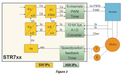
Figure 3 represents a new STR7 device which is being developed for ST’s ARM7 processor-based product line, which satisfies the requirement outlined previously. It includes:
- SPTimer (Synchronizable PWM Timer) to perform high-end PWM generation: based on 16-bit timer and able to go down to 16.6ns time resolution for optimal voltage reconstruction
- capability to produce center-aligned or edge-aligned PWM patterns
- internal programmable dead time generator and an emergency Stop protection for inverter fault management.
- to ease the software processing, it has multiple interrupt sources, a program mable reload rate and “smoke inhibit” protections to prevent a software run away from modifying the system critical peripheral configuration registers.

This SPTimer is also available as a general purpose timer with two input captures, two output compares and an encoder dedicated mode to minimize the software overhead when having using such a sensor. It offers x2 or x4 resolution, automatic direction management and the possibility to program the number of lines of the chosen model, so that the angular rotor position can be directly read on the counter registers.
Finally it embeds a 3ìs 10-bit ADC with auto scan capabilities for motor current measurements. This list is not exhaustive: numerous timers, communication interfaces and smart peripherals are also onboard to take care of non-motor control related tasks to be handled by the MCU: connectivity, power factor correction, dissipative braking…
STMicroelectronics is clearly committed to the motor control market, and is one of the sole semiconductor manufacturers able to provide the complete motor control portfolio, from the fast diodes to the processors, including the high voltage gate drivers and the switches. To satisfy the demand of “greener” motors and high performance drives, we’re building up a complete ARM processor-based product line which will help demystifying vector control algorithms. This should soon obsolete today’s common DSP paradigm. And impose a new one: why would anyone want to consume the time to implement advanced motor control on proprietary architectures while standard ARM processor-based MCUs are able to fit the requirements?
Related Semiconductor IP
- HBM4 PHY IP
- Ultra-Low-Power LPDDR3/LPDDR2/DDR3L Combo Subsystem
- HBM4 Controller IP
- IPSEC AES-256-GCM (Standalone IPsec)
- Parameterizable compact BCH codec
Related Articles
- Control an FPGA bus without using the processor
- Advanced BLDC Motor Control using Freescale Ultra Reliable MPC5676R/MPC5674F MCU
- Simplifying SoC design with the Customizable Control Processor
- How to use FPGAs for quadrature encoder-based motor control applications
Latest Articles
- Pipeline Stage Resolved Timing Characterization of FPGA and ASIC Implementations of a RISC V Processor
- Lyra: A Hardware-Accelerated RISC-V Verification Framework with Generative Model-Based Processor Fuzzing
- Leveraging FPGAs for Homomorphic Matrix-Vector Multiplication in Oblivious Message Retrieval
- Extending and Accelerating Inner Product Masking with Fault Detection via Instruction Set Extension
- ioPUF+: A PUF Based on I/O Pull-Up/Down Resistors for Secret Key Generation in IoT Nodes