Image Processing - RTL Implementation of Median Filtering for Image Denoising
Vardhana M, Design Engineer, NXP Semiconductors, India
Abstract
This article explains step by step implementation of Median Filtering Algorithm in Verilog. This filtering technique is then applied to noisy image for denoising. This article also explains simple Verilog based testbench and Matlab scripts for image pre/post processing operation for verifying the same.
I. INTRODUCTION
Image processing is one of the major field which is gaining more and more importance in day to day life. Starting from simple image classification to complex autonomous driving, image processing is playing a very significant role.
In this article an effort has been made to explain the RTL implementation of Median filtering for image denoising.
Median filter is a nonlinear filtering technique often used to remove noise from a signal or image. The noise reduction is a pre-processing step in any of the image processing operation to ensure better results at late stages of processing.
The main process of median filter is to run through the signal entry by entry and replacing the each entry with the median of neighboring entries. Typically for 2D signal as for an image, the window of particular size is chosen and each window is scanned throughout image. While scanning, the middle pixel is replaced by the median of pixels in the window. For simplicity we have considered a 3x3 window. RTL implementation of median filtering is carried out using Verilog HDL, which computes the median of input pixel value and returns the resultant.
Matlab scripting is carried out for capturing the image and converting it to binary for Verilog processing and for representing the processed image.
II. DETAILED IMPLEMENTATION
This section would describe the detailed implementation of image denoising. Figure 1 presents the general block diagram for image denoising.
It consists of an camera unit, to capture the real time images/video and provide it for denoising. It also consists of an VGA monitor for visual aid.
RTL implementation shall include an camera controller for driving the necessary values for acquiring the object. RTL shall also include a VGA controller for driving the VGA signals for visual aid.
In this article, the job of camera, camera controller, VGA controller, VGA Monitor are modelled using Matlab Scripts. The core of the denoiser would include a memory to store the acquired image, controller for implementing windowing and a median filter for performing median operation. The memory and controller behavior is modelled as a Verilog testbench and median filter is an synthesizable Verilog module.
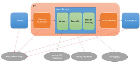
Fig.1. General Block Diagram for Image Denoising
Figure 2 presents the Matlab preprocessing script, which would acquire an image from local directory and resize the image for a given size. Code fragment #1 is used to obtain the image from the local directory which would pop up a file search directory and user chooses from available set of images.
Acquired image is then converted to a gray scale image to ease the processing by reducing the three channel(RGB) to one single channel.
After the conversion of the image to gray scale, image is then resized to fit into the memory which is 100x100 as presented in the code fragment #2.
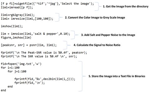
Fig.2. Matlab Pre-Processing
Code fragment #3 shows the addition of salt and pepper noise to the resized image. Signal to noise ratio is then calculated for performance analysis. The noisy image is then stored into a text file in binaries, which will be then stored in the design memory for processing as in #5.
Once the pre-processing operation is done, the next step is to obtain the necessary pixel in a 3x3 window from the memory and proceed with median calculation. This is implemented by means of Verilog test bench as shown in below figure 3.
In real time, this memory and controller would be a part of design. The camera would continuously acquire the image and storing in a memory, which is then processed by the controller for denoising the noisy image and display it via VGA interface.
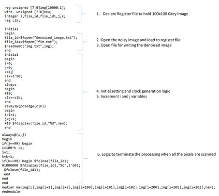
Fig.3. Verilog Testbench
Code fragment #1 declares the memory as an register file of width 10000, so as to accumulate the 100x100 grey scale image.
Code fragment #2 and #3 describers the necessary file processing operation carried out to load the image binaries into the testbench memory and file handles for post processing.
Code fragment #4 and #5 implements the necessary clock generation and counter implementation, to scan all the 100x100 pixels in memory.
Code Fragment #6 implements storing the denoised image on to a text file for post processing operation. In real time, the processed pixel will be displayed in a VGA monitory by means of VGA controller.
Figure 4 presents the Verilog RTL for median filtering.
The job of this module is to obtain the nine eight bit pixel values and return the median of these pixels.
Median is calculated by means of merge sort algorithm.
The nine pixels are first sorted in ascending order and then, the center most value provides the median.
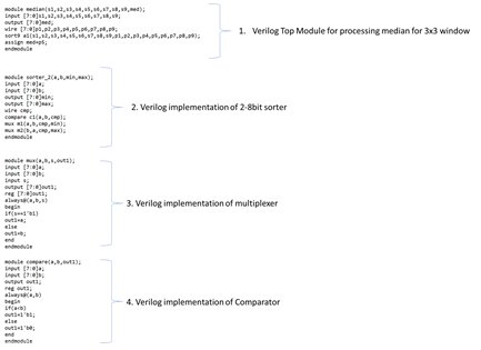
Fig.4. Verilog RTL for Median Filtering
The design consists of an nine input sorter, which is then implemented by means of several 2 input sorters as in code fragment #2. Code fragments #3 and #4 describes the implementation of comparator and a multiplexer.
Once the simulation is complete, the processed image is stored as text file which is then processed by Matlab.
Figure 5 presents the Matlab post processing script.
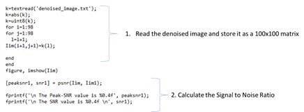
Fig.5. Matlab Post-Processing
Denoised image is converted back to 2D matrix and Signal to Noise Ratio is calculated as in code fragments #1 and #2.
III. SIMULATION RESULTS
This section would describe the simulation results of the design.
Figure 6 shows the image acquired using Matlab and noisy image after adding Salt and Pepper noise.

Fig.6. Image Pre-Processing Results
The noise image is then processed using Verilog and is presented in figure 7.
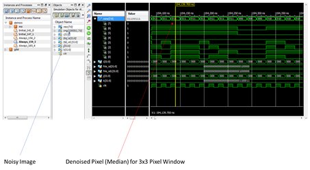
Fig.7. Median Filtering Simulation Result
Denoised image is the post-processed using Matlab scripts and is presented in figure 8.
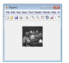
Fig.8. Image Post-Processing Result
Table 1 presents the comparison of results for Noisy and Denoised image. It can be seen that the is significant increase in the Signal to Noise Ratio after denoising.
Table.1. Comparison Result
| Noisy Image | Denoised Image | |
| PSNR | 15.1236 | 26.7612 |
| SNR | 6.4697 | 18.1074 |
Related Semiconductor IP
- HBM4 PHY IP
- Ultra-Low-Power LPDDR3/LPDDR2/DDR3L Combo Subsystem
- HBM4 Controller IP
- IPSEC AES-256-GCM (Standalone IPsec)
- Parameterizable compact BCH codec
Related Articles
- An 800 Mpixels/s, ~260 LUTs Implementation of the QOI Lossless Image Compression Algorithm and its Improvement through Hilbert Scanning
- A Real-Time Image Processing with a Compact FPGA-Based Architecture
- Using vector processing for HD video scaling, de-interlacing, and image customization
- Design and FPGA Implementation of an Interpolative Neural Network for Digital Image Zooming
Latest Articles
- Pipeline Stage Resolved Timing Characterization of FPGA and ASIC Implementations of a RISC V Processor
- Lyra: A Hardware-Accelerated RISC-V Verification Framework with Generative Model-Based Processor Fuzzing
- Leveraging FPGAs for Homomorphic Matrix-Vector Multiplication in Oblivious Message Retrieval
- Extending and Accelerating Inner Product Masking with Fault Detection via Instruction Set Extension
- ioPUF+: A PUF Based on I/O Pull-Up/Down Resistors for Secret Key Generation in IoT Nodes