Mixel IP
Filter
Compare
11
IP
from
1
vendors
(1
-
10)
-
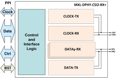
MIPI D-PHY RX+ (Receiver) IP
- The MIPI® D-PHY RX+ is a proprietary implementation of the MIPI Camera Serial Interface 2 (CSI-2) and Display Serial Interface (DSI) D-PHY Receiver.
- It is optimized to achieve full-speed production testing, in-system testing, and higher performance compared to traditional configurations, while reducing area and standby power.
-
MIPI D-PHY TX+ (Transmitter)
- The MIPI® D-PHY TX+ is a proprietary implementation of the MIPI Camera Serial Interface 2 (CSI-2) and Display Serial Interface (DSI) D-PHY Transmitter.
- It is optimized to achieve full-speed production testing, in-system testing, and higher performance compared to traditional configurations, while reducing area and standby power.
-
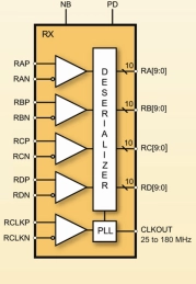
LVDS Deserializer IP
- The MXL-DS-LVDS is a high performance 4-channel LVDS Deserializer implemented using digital CMOS technology.
- Both the serial and parallel data are organized into four channels. The parallel data can be 7 or 10 bits wide per channel. The input clock is 25MHz to 165MHz. The De-serializer is highly integrated and requires no external components.
-
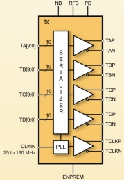
LVDS Serializer IP
- The MXL-SR-LVDS is a high performance 4-channel LVDS Serializer implemented using digital CMOS technology. Both the serial and parallel data are organized into four channels.
- The parallel data width is programmable, and the input clock is 25MHz to 165MHz. The Serializer is highly integrated and requires no external components.
-
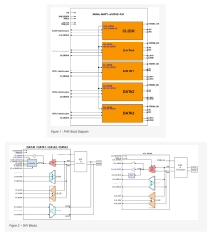
MIPI D-PHY/LVDS Combo Receiver IP
- The MXL-LVDS-MIPI-RX is a high-frequency, low-power, low-cost, source-synchronous, Physical Layer that supports the MIPI® Alliance Standard for D-PHY and compatible with the TIA/EIA-644 LVDS standard.
- The IP is configured as a MIPI slave and consists of 5 lanes: 1 Clock lane and 4 data lanes, which make it suitable for display serial interface applications (DSI).
-
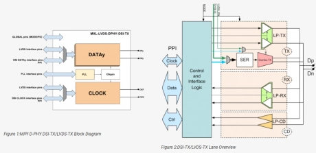
MIPI D-PHY/LVDS Combo Transmitter IP
- The MXL-LVDS-DPHY-DSI-TX is a combo PHY that consists of a high-frequency low-power, low-cost, source-synchronous, Physical Layer supporting the MIPI® Alliance Standard for D-PHY and a high performance 4-channel LVDS Serializer implemented using digital CMOS technology.
- In LVDS mode, both the serial and parallel data are organized into 4 channels. The parallel data is 7 bits wide per channel. The input clock is 25MHz to 150MHz. The serializer is highly integrated and requires no external components. The circuit is designed in a modular fashion and desensitized to process variations. This facilitates process migration, and results in a robust design.
-
MIPI C-PHY/D-PHY Combo IP
- The MIPI C/D-PHY combo IP is a high-frequency low-power, low cost, physical layer compliant with the MIPI® Alliance Standard for C-PHY and D-PHY.
- The PHY can be configured as a MIPI Master or MIPI Slave, supporting camera interface CSI-2 v1.2 or display interface DSI v1.3 applications in the D-PHY mode. It also supports camera interface CSI-2 v1.3 and display interface DSI-2 v1.0 applications in the C-PHY mode.
-
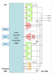
MIPI C-PHY
- The C-PHY configuration consists of up to three lane modules and is based on 3-Phase symbol encoding technology, delivering 2.28 bits per symbol over three-wire trios and targeting a maximum rate of 2.5 Gsps, 5.7Gbps.
- The C-PHY is partitioned into a digital module – CIL (Control and Interface Logic) and a mixed-signal module. The PHY IP is provided as a combination of soft IP views (RTL, and STA Constraints) for the digital module, and hard IP views (GDSII/CDL/LEF/LIB) for the mixed-signal module.
-
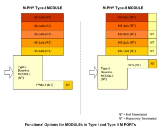
MIPI M-PHY IP
- The MIPI M-PHY is a high-frequency low-power, Physical Layer IP that supports the MIPI® Alliance Standard for M-PHY.
- The IP can be used as a physical layer for many applications, connecting flash memory-based storage, cameras and RF subsystems, and for providing chip-to-chip inter-processor communications (IPC).
-
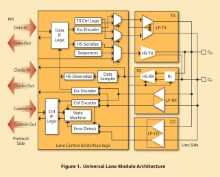
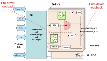
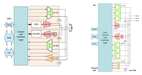
MIPI D-PHY IP
- The D-PHY is partitioned into a Digital Module – CIL (Control and Interface Logic) and a Mixed Signal Module. It is provided as a combination of Soft IP views (RTL, and STA Constraints) for Digital Module, and Hard IP views (GDSII/CDL/LEF/LIB) for the Mixed Signal Module.
- This unique offering of Soft and Hard IP permits architectural design flexibility and seamless implementation in customer-specific design flow.