IP for SMIC
Welcome to the ultimate
IP
for
SMIC
hub! Explore our vast directory of
IP
for
SMIC
All offers in
IP
for
SMIC
Filter
Compare
1,115
IP
for
SMIC
from
38
vendors
(1
-
10)
-
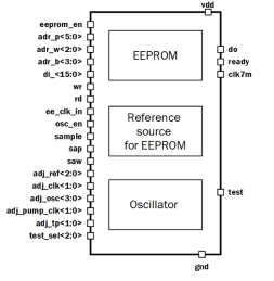
1Kbyte EEPROM IP with configuration 64p8w16bit
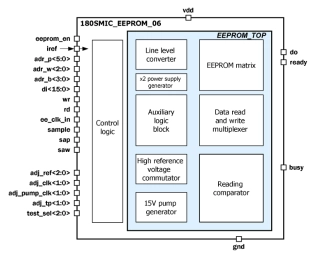
- The block is a nonvolatile electrically erasable programmable read-only memory (EEPROM) with volume 1Kbyte (16(bit per word) x 8(words per page) x 64(pages)) with single-bit output data and parallel write data in one word.
- Write EEPROM page data comes to input di<15:0> and write process execute if signal wr=“1”.
-
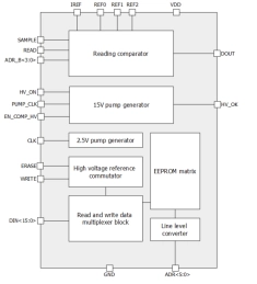
1024-bit EEPROM IP with configuration 32p2w16bit
- The block is a nonvolatile electrically erasable programmable read-only memory (EEPROM) with volume 1024 bits (16(bit per word) x 2(word per page) x 32(page)), which is organized as 32 pages of 2 words by 16 bit with single-bit output data and parallel write data.
- Data writing in EEPROM consists of 2 phases - erasing and writing.
-
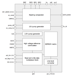
512-bit EEPROM IP with configuration 16p2w16bit
- The block is a nonvolatile electrically erasable programmable read-only memory (EEPROM) with volume 512 bits (16(bit per word) x 2(word per page) x 16(page)), which is organized as 16 pages of 2 words by 16 bit with single-bit output data and parallel write data.
- Write EEPROM page data comes to input D0<15:0> and write by words to latch through the signal SAMPLE, while the signal write in a state of «1». The address of a word written down in latches is defined by two low bits of the bus adr_bl<1:0>.
-
1Kbyte Embedded EEPROM with configuration 64p8w16bit
- SMIC EEPROM CMOS 0.18 um
- 1Kbyte of available memory 16(bit per word) x 8(words per page) x 64(pages) bit
-
50MHz to 800MHz Integer-N RC Phase-Locked Loop on SMIC 55nm LL
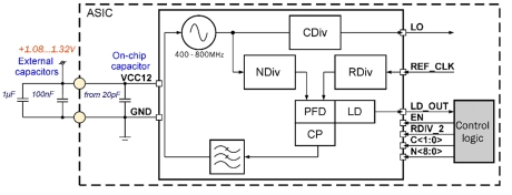
- 055SMIC_PLL_01 forms clock output signal with frequency from 50 to 800MHz.
- It consists of the ring VCO with frequency from 400 to 800MHz, a programmable feedback divider, a low noise digital phase noise detector (PFD), a precision charge pump (CP) with internal loop filter, lock detector (LD) and programmable clock divider to obtain a required output frequency.
- LO output signal is CMOS compatible.
-
-
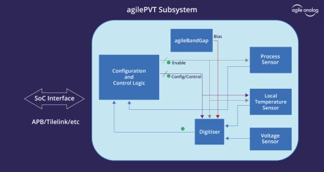
PVT Sensor Subsystem
- Start-up time: Typ 20us
- Current consumption: Max 25uA
- Industry standard digital interface
- Fully integrated macro
- Standard AMBA APB interface
-
Embedded flash IP, 1.5V/5V SMIC 90nmBCD
- Supports high temperature and long retention life time for severe automotive requirement
- Low power in Program/Erase operation for power critical applications
- Requires few (2~3) additional masks
- No change to SPICE model of Standard CMOS process, for re-using existing design and IP

-
Embedded flash IP, 1.32V/3V PSMC 90nm
- Supports high temperature and long retention life time for severe automotive requirement
- Low power in Program/Erase operation for power critical applications
- Requires few (2~3) additional masks
- No change to SPICE model of Standard CMOS process, for re-using existing design and IP
-
-40°C to +85°C Low power temperature sensor
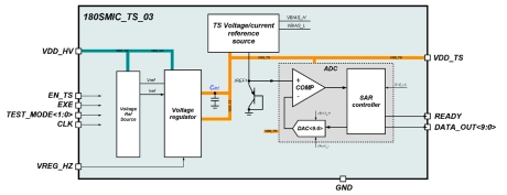
- The 180SMIC_TS_03 is a unique stand-alone solution intended to continuously monitor IC status.
- Temperature detector consists of temperature sensor unit (the voltage at which is directly proportional to the temperature), analog core, SAR controller as calculation center for temperature measurements, as well as an internal voltage regulator, with an output level of 1.25V.
