Camera Link IP
Filter
Compare
60
IP
from
21
vendors
(1
-
10)
-
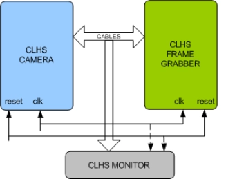
Camera Link HS Verification IP
- Full Camera Link HS transmitter device and receiver device functionality.
- Supports Transmitter and Receiver Mode.
- Supports following message packets,
- 7 different pulse (trigger) modes of operation
-
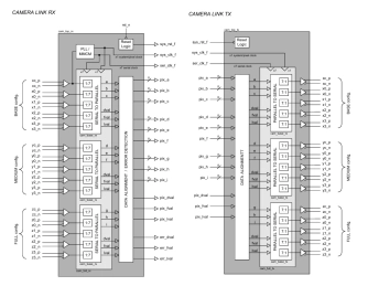
Camera Link Interface
- The Camera Link® IP Core is a high-speed LVDS transmitter / receiver pair that conforms to the standard Camera Link protocol originally developed by National Semiconductor Corp®.
- The design is comprised of an independent transmitter and receiver that may be implemented separately or together as a single transceiver unit. The IP Core may be used in either the BASE, MEDIUM or FULL configurations as defined in the Camera Link specification.
-
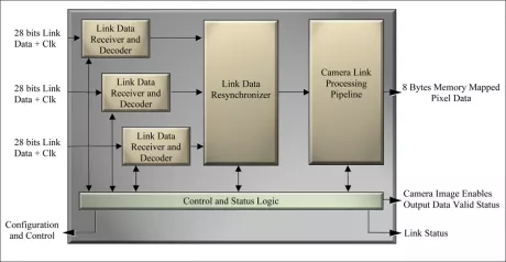
Camera Link Frame Grabber Channel Link Data Processor
- Inclusive of all Camera Link defined camera configurations including the proposed 80 bit extensions which utilize one to three Channel Link or equivalent devices.
- Supports single camera or two independent base cameras for multi-view or 3D stereo applications.
- Fully synchronous pipeline architecture supports high speed implementation in low cost logic devices.
- Dynamic reconfiguration of the processing chain via register interface in addition to a user selected default setup.
-
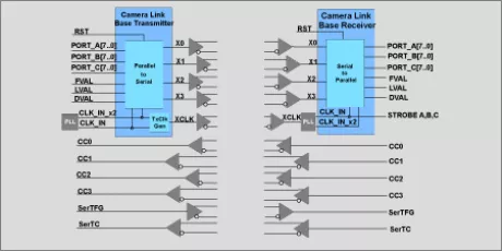
Camera Link Transceiver
- Supports 8-bit, 10-tap Base, Medium & Full Camera Link interfaces
- Supports 64-bit and 80-bit extended Full configurations
- Camera and Frame Grabber configurations
- 7:1 Camera Link Serializer/Deserializer (SerDes)
-
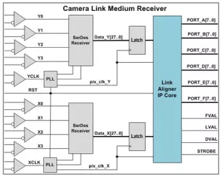
Camera Link Aligner
- Auto Link Aligner for 8-bit, 10-tap Base, Medium & Full Frame Grabber configurations
- Supports 64-bit and 80-bit extended Full configurations
- Pixel clock rates to 85 MHz.
- Power Over Camera Link (PoCL) SafePower
-
Multi-PHY Receiver Link Controller
- CD12842M8LRM3BM4AIP312P5 is a link IP that allows you to link a camera module or CMOS image sensor (CIS) to a host system.
- This LINK IP is a soft macro IP that has the function of converting MIPI CSI2 protocol or other interface protocol to the data for application layer.
-
MIPI D-PHY TX/CSI2 Link Controller
- CD12631S4TIP is a link IP that allows you to link a camera module or CMOS image sensor (CIS) to a host system.
- This LINK IP is a soft macro IP that has the function of converting input data to MIPI CSI2 protocol.
-
Camera Combo Receiver - 5.0Gbps 8-Lane - TSMC 12FFC, 7FF
- The CL12842M8RM3AM5AIP5000 is an ideal means to link Camera Modules or CMOS Image Sensor (CIS) to ISP (Imaging Signal Processor) and DSP.
- The CL12842M8RM3AM5AIP5000 is designed to support data rate in excess of maximum 5Gbps utilizing SLVS-EC ver.2.0 / MIPI D-PHY ver.1.2 / HiSPi / sub-LVDS / CMOS 1.8V interface specification.
-
Camera Combo Receiver - 2.5Gbps 8-Lane - TSMC 28nm HPC
- The CL12832M8R2JM3QIP2500 is an ideal means to link Camera Modules or CMOS Image Sensor (CIS) to ISP (Imaging Signal Processer) and DSP.
- The CL12832M8R2JM3QIP2500 is designed to support data rate in excess of maximum 2.5Gbps utilizing SLVS-EC / MIPI D-PHY v-1.2/ CMOS 1.8V interface specification.
-
Camera Combo Receiver - 5.0Gbps 8-Lane
- The CL12822M4R2JM2LIP5000 is an ideal means to link Camera Modules or CMOS Image Sensor (CIS) to ISP (Imaging Signal Processer) and DSP.
- The CL12822M4R2JM2LIP5000 is designed to support data rate in excess of maximum 5.0Gbps utilizing SLVS-EC ver.2.0 / MIPI D-PHY v2-1 interface specification. The CL12822M4R2JM2LIP5000 can change Interface type to same PAD for changing mode.