Corner Case Scenario Generation (CCSG) Tool: A Novel Approach to find corner case bugs in next generation SoCs
Naveen Jakhar, ITS Officer, Department of Telecommunications, Government of India.
Abstract:
The next generation SoCs are supporting multi-power domains and multi- mode operations features for supporting aggressive operational functionality and reduced power numbers. There are various asynchronous events like external resets, external interrupts, external wakeups, clock failures etc. which might occur during the windows of ongoing mode transitions in the actual use-case scenario of the SoC. So, the combination of these events during mode transitions bring an entropy and uncertainty in the design which needs to be thoroughly verified. The conventional SoC level verification approach for these asynchronous events does not cover how these events are going to affect the mode transitions. Even addition of randomization of these events during mode transitions does not provide fool proof solution. In this article, we will be highlighting the grey areas and corner case bugs which are reported by the customers when they use these SoCs in their actual use-cases and how to do the robust verification of the corner case scenarios during pre-silicon SoC verification using Corer Case Scenario Generation Tool.
Problem Statement:
The conventional approaches of SoC level verification of covering mode transitions do not verify the impact of asynchronous events like external resets, external interrupts, external wakeups, clock failures etc. on the mode transitions. As a result of this, bugs remain uncovered during SoC pre-silicon verification and they are often reported by the customers to the SoC designers. Let us try to understand the gravity of such uncovered bugs with an example.
Today’s SoCs are having various modes of operations. Say, an SoC is having three full power modes of operations, namely RUN0, RUN1 & RUN2 and one low power mode of operation which is called STOP mode. The mode transition from current mode of operation to target mode of operation is broadly divided into 4 steps.
- First step: The software writes the target mode’s system configurations in the Mode Control Module (MCM).
- Second step: The software writes the security key to the MCM.
- Third step: The software writes inverted security key to the MCM.
- Fourth step: The mode transition happens from current mode to target mode.
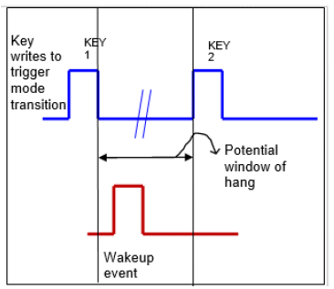
Now, consider a mode transition sequence: RUN0-> RUN1-> RUN2-> STOP. The customer reported a design bug in this mode transition sequence when we are making a transition from RUN2 to STOP mode. The issue reported says that if an external wakeup event is detected one clock cycle before the inverted security key is written to Mode Control Module (MCM) to initiate the transition to STOP, SoC enters RUN1 mode.
Software programmed sequence: RUN0-> RUN1-> RUN2 (current mode) -> STOP (target mode)
Design bug scenario: RUN0-> RUN1-> RUN2 (current mode) -> STOP (target mode) -> RUN1 (current mode)

Fig 1. Example of corner-case mode transition failure
Root Cause Analysis:
While doing the root cause analysis, these are the possible cases:
If the wakeup had caused an abort to the ongoing mode transition, the sequence would have been like this:
Wakeup causing abort: RUN0-> RUN1-> RUN2 (current mode) -> STOP (target mode) -> RUN2 (current mode)
If the wakeup had not affected the ongoing mode transition, then SoC would have entered the target mode and the sequence would have been like this:
Mode transition completion: RUN0-> RUN1-> RUN2 (current mode) -> STOP (target mode) -> STOP (current mode)
When the issue was analysed, it came out that the issue manifested itself because there was one cycle gap between the new_mode_request being generated and the assertion of mode transition_signal inside MCM and hence a single cycle window where even though MCM accepted a new mode request, the mode_transition active signal was not updated thus suggesting no new transition ongoing when actually it was. Because of this any wakeup event hitting the SoC during this one cycle caused the previous mode (RUN1) itself to be loaded as the target mode.
CCSG Tool:
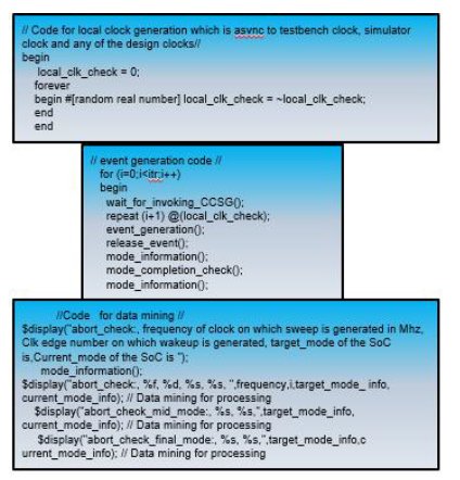
After doing this root cause analysis, we felt the need of an automated tool for generating and verifying these corner case scenarios. But adding randomization of asynchronous events is not the solution, because we can miss one cycle even after doing randomization. For the robust verification, we need to insert these asynchronous events so as to cover the entire windows of ongoing mode transitions. The CCSG tool gives a capability to the verification engineer to firstly hit all such possible scenarios using its precise sweeping of events and then based on intelligent post-processing (also embedded in the tool), derive and present meaningful graphical data to the user for first-glance deduction of potential error scenarios. CCSG has been coded in Verilog and it is totally independent to testbench and environment. So, it can be easily plugged in and used in verification as well as validation environment. Fig2 shows the Verilog snippet from the code used in CCSG.
- CCSG tool generates high precision sweeping events on the edges of a test clock which is called local_clk_check as shown in the below code. This clock is asynchronous to the testbench clock, simulator clock and all the clocks being used as system clocks.
- The event type: external reset or external wakeup or external interrupt or clock failure is decided by the user.
- itr means the iteration count. It is to be decided by the user. The sweeping continues till the time we have completely covered the entire window of mode transition.
- The intelligent post processing finally generates the excel sheet showing cumulative occurrence of events in system and distribution of those into the total counts of successful vs failed mode transitions.

Fig2. Snippet from Verilog code used in CCSG
The verification engineer needs to write a simple test for doing the mode transition, say fromRUN mode to STOP mode. Then he/she needs to provide the inputs to CCSG as mentioned insteps 1 to 3.

Fig3. Waveforms using CCSG : abort mode transition
Fig.3 shows that a mode transition from RUN to STOP mode has been programmed by the software. But an async external wakeup event causes the mode transition to abort and the SoC stays in RUN mode.
The output of the CCSG tool is as follows:
| Abort Check | Frequency (MHz) | clk edge number | actual target mode | current mode | Expected target mode |
| check1 | 30 | 0 | RUN | RUN | STOP |
| check2 | 30 | 1 | RUN | RUN | STOP |
| check3 | 30 | 2 | RUN | RUN | STOP |
| check4 | 30 | 3 | RUN | RUN | STOP |
| check5 | 30 | 4 | RUN | RUN | STOP |
| check6 | 30 | 5 | RUN | RUN | STOP |
Fig4. Output of CCSG
Conclusion:
CCSG tool provides an easy way to find corner case bugs present in the design of complex SoCs during pre-silicon verification stage itself which are otherwise left uncovered in the design and often reported by the customers. So, CCSG tool adds a value to the robust verification done by the SoC verification engineers and results in good quality silicon.
Related Semiconductor IP
- HBM4 PHY IP
- Ultra-Low-Power LPDDR3/LPDDR2/DDR3L Combo Subsystem
- MIPI D-PHY and FPD-Link (LVDS) Combinational Transmitter for TSMC 22nm ULP
- HBM4 Controller IP
- IPSEC AES-256-GCM (Standalone IPsec)
Related Articles
- Staged Scenario Generation For SoC Verification
- eTBc: A Semi-Automatic Testbench Generation Tool
- DDGEN: An Automated Device Driver Generation Tool for Embedded Systems
- Automatically Retargeting Hardware and Code Generation for RISC-V Custom Instructions
Latest Articles
- ElfCore: A 28nm Neural Processor Enabling Dynamic Structured Sparse Training and Online Self-Supervised Learning with Activity-Dependent Weight Update
- A 14ns-Latency 9Gb/s 0.44mm² 62pJ/b Short-Blocklength LDPC Decoder ASIC in 22FDX
- Pipeline Stage Resolved Timing Characterization of FPGA and ASIC Implementations of a RISC V Processor
- Lyra: A Hardware-Accelerated RISC-V Verification Framework with Generative Model-Based Processor Fuzzing
- Leveraging FPGAs for Homomorphic Matrix-Vector Multiplication in Oblivious Message Retrieval