Building Process For the C/C++ Program on Complex SoCs
Amitav Halder, Arunendra Tomar, Umesh Pratap Singh (Freescale Semiconductors)
Introduction:
SoCs environment includes lots of modules/IP and cores/processors. In the whole environment different languages/scripts or methodologies used. In a typical SoCs setup, stimulus to modules is provided using the.c/cpp files through different interfaces. In this .c/cpp building process includes different phases/stages. And stimulus is generated corresponding to what is in .c/cpp, that stimulus is provide to IP/modules through various interfaces and core.
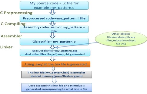
When the C code runs there is four stages of C code building process which utilizes different ‘tools’ such as a preprocessor, compiler, assembler, and linker. Finally we get executable/.hex file from .c file.
Here are the stages which are involved in C code building process in order regardless of the operating system/compiler.
Preprocessing :
Preprocessing is the first stage of any C code building. It processes include-files, conditional compilation instructions and macros. Here we get “make errors” if there is some issue regarding the include files/macros.If some include files/macros are missing than there is “make_errors” or such errors are called make errors. For example #define my_dma_en, if this “my_dma_en” deifne is used without “#define my_dma_en”, than there will be make error for “my_dma_en” as undefined “my_dma_en”
Compilation:
Compilation is the second stage of any C code building . It takes the output of the preprocessor, and the source code, and generates assembler source code. On this stage .asm files generated. If there is syntactical errors in source code than such errors are called compilation error.
Assembly:
Assembly is the third stage of C code building . It takes the assembly source code and produces an assembly listing with offsets. The assembler output is stored in an object file.In this process .obj made from .asm.
Linking :
Linking is the final stage of C code building. It takes one or more object files or libraries as input and combines them to produce a single (usually executable) file. In this process .exe made from .obj.

Fig1: C/CPP BIULDING FLOW ON SoCs
NOTE: In UNIX/Linux, the executable or binary file doesn’t have extension whereas in Windows the executables for example may have .exe, .com and .dll. similarly file extensions can be .o or .obj for object file and .s or .asm for assembly files.
WHAT ARE OBJECT FILES AND EXECUTABLE FILES:
Assembler and linker generates the .obj or .o and .exe respectively. An object and executable come in several formats such as ELF (Executable and Linking Format) and COFF (Common Object-File Format) depending on OS .
An object file is basically a file containing machine language instructions and data in a form that the linker can use to create an executable program. Each routine or data item defined in an object file has a corresponding symbol name by which it is referenced. A symbol generated for a routine or data definition can be either a local definition or global definition. Any reference to a symbol outside the object file is known as an external reference.
These object files have areas called sections. Sections can hold executable code, data, dynamic linking information, debugging data, symbol tables, relocation information, comments, string tables, and notes.
Some sections are loaded into the process image and some provide information needed in the building of a process image while still others are used only in linking object files. For example .txt section or .bss section.
By default , the format (.obj or .o) is unreadable format but can be made in .obj.txt format to make it readable format.
Here are the details for important fields of object files:
.text :This section contains the executable instruction codes and is shared among every process running the same binary. This section usually has READ and EXECUTE permissions only. This section is the one most affected by optimization.
.bss: BSS stands for ‘Block Started by Symbol’. It holds un-initialized global and static variables. Since the BSS only holds variables that don't have any values yet, it doesn't actually need to store the image of these variables. The size that BSS will require at runtime is recorded in the object file, but the BSS (unlike the data section) doesn't take up any actual space in the object file.
.data: Contains the initialized global and static variables and their values. It is usually the largest part of the executable. It usually has READ/WRITE permissions.
.reloc: Stores the information required for relocating the image while loading.
ELF(Executable and Linking Format ) is binary format, which is used in Unix and Linux systems
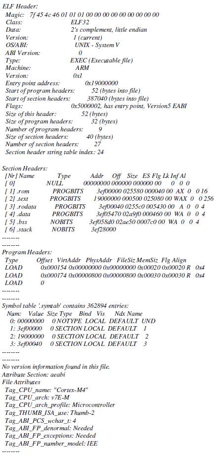
For example: my_pattern.elf(its format is unreadble) and my_pattern.elf.txt(its is in readable format) which contains below:
Note: The below given elf is for ARM core .

NOTE: ELF is used on Linux systems, while COFF is used on Windows systems.
COFF:The COFF (Common Object File Format) files may have multiple sections, each prefixed by a header. The number of sections is limited. The COFF specification includes support for debugging but the debugging information was limited. There is no file extension for this format.
ELF:The ELF (Executable and Linking Format) is similar to COFF in being organized into a number of sections, but it removes many of COFF's limitations. ELF used on most modern Unix systems, including GNU/Linux, Solaris and Irix. Also used on many embedded systems.
Executable and Linking Format (ELF) is binary format, which is used in Unix and Linux systems.
It is a format for storing programs or fragments of programs on disk, created as a result of compiling and linking.
ELF not only simplifies the task of making shared libraries, but also enhances dynamic loading of modules at runtime.
LINKING:
Because there are various object files which are included as references to each others code and/or data, so various locations, these are combined during the link time.
For example: the object file that has main() includes calls to functions funct() and printf().
After linking all of the object files together, the linker uses the relocation records to find all of the addresses that need to be filled in.
Fig2:Files generated in c building flow on SoCs
SHARED OBJECTS:
In a typical system, a number of programs will be running. Each program relies on a number of functions, some of which will be standard C library functions, like printf(), malloc(), strcpy(), etc. and some are non-standard or user defined functions.
If every program uses the standard C library, it means that each program would normally have a unique copy of this particular library present within it.This result in wasted resources, degrade the efficiency and performance. So it is better to have each program reference the common (because the C library is common,) one instance of that library, instead of having each program contain a copy of the library.
This is implemented during the linking process where some of the objects are linked during the link time whereas some done during the run time (deferred/dynamic linking).
STATICALLY LINKING:
The term ‘statically linked’ means that the binding between the program and the particular library is fixed and known at link time before the program run. This binding can’t be changed, unless we re-link the program with a new version of the library.
Programs that are linked statically are linked against archives of objects (libraries) that typically have the extension of .a. e.g. libc.a
The limitation of this technique is that the executable is quite big in size, all the needed information need to be brought together.
DYNAMICALLY LINKING:
The term ‘dynamically linked’ means that the binding between the program and the shared object is done at runtime that is before the program starts, the appropriate shared objects are found and bound.
The linker places information into the executable that tells the loader which shared object module the code is in and which runtime linker should be used to find and bind the references.
Programs that are linked dynamically are linked against shared objects that have the extension .so. e.g. libc.so
Advantages :
Program files (on disk) become much smaller because they need not hold all necessary text and data segments information. It is very useful for portability.
In combination with virtual memory, dynamic linking permits two or more processes to share read-only executable modules such as standard C libraries. Using this technique, only one copy of a module needs be resident in memory at any time, and multiple processes, each can executes this shared code (read only). This results in a considerable memory saving, although demands an efficient swapping policy.
LOADING:
In Linux processes loaded from a file system (using either the execve() or spawn() system calls) are in ELF format. This elf format contains various sections such as .init,.text,.bss.got,.data,.ctors,.dtors as shown in above elf format(my_pattern.elf.txt)
When the .exe(executable) runs , before running this need to load into memory.
This is done by the loader, which is generally part of the operating system. The loader does the following things (from other things):
Memory and access validation - Firstly, the OS system kernel reads in the program file’s header information and does the validation for type, access permissions, memory requirement and its ability to run its instructions. It confirms that file is an executable image and calculates memory requirements.
Process setup includes:
- Allocates primary memory for the program's execution.
- Copies address space from secondary to primary memory.
- Copies the .text and .data sections from the executable into primary memory.
- Copies program arguments (e.g., command line arguments) onto the stack.
- Initializes registers: sets the esp (stack pointer) to point to top of stack, clears the rest.
- Jumps to start routine, which: copies main()'s arguments off of the stack, and jumps to main().
i.e. The operating system logically copies a file’s segment to a virtual memory segment according to the information provided in the program header table. The OS can also use segments to create a shared memory resource.
Address space is memory space that contains program code, stack, and data segments or in other word, all data the program uses as it runs. The memory layout, consists of three segments (text, data, and stack).
C EXECUTION FLOW IN SoCs:
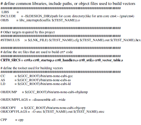
In a SoCs , there is lots of modules and large environment setup exists. So we need make_file to compile and run the pattern with the whole environment .In SoCs, there is core/processor which gives the stimulus to module using the C file. In the make file (like makefile.stimulus and _makefile.defs_) have to provide the relevant switches.

How core/processor come to know that from which function/part of C in SoCs execution will starts:
As shown above , using make file we provide the core directives and related switches.
In the core/processor directory, there is “crto.s” file which gives the information about the startup code.
The entry point of the C runtime-startup code is given in “crto.s” in typcal SoCs. In a typical system, this will be called by the target-specific startup code after it has initialized the target.
i.e. the entry point is the location at which execution begins in the a.out file.
The crto.s looks like: (this is of ARM core)

And power PC core ‘s crto.s looks like:

Because of this “BL pre_main_init @ call the C code” core will start to execute this function. This function “pre_main_init” itself calls “main” and “post_main”.
NOTE: the functions “pre_main and post_main” are not generic ,this are self made as per SoC environment, CORE may directly start to execute “main” of C file.
Thus, in this way core gets the entry point and execute the C in SoC environment.
In SoC setup,when C program runs, .exe/.elf is made after going through the C building processes i.e. making ->compiling and linking. In SoC setup this .exe/elf is converted into a formatted hex which is loaded at desired location(sram,flash or gram).
This “hex ” file is made so that,core can execute the hex from the desired location(sram,flash or gram).
NOTE:In this hex, there is information embedded of the whole SoC environment(core files,all modules,C files and SoC setup files).
Therefore, In SoC environment, a “hex” file is generated from .elf/.exe. Core executes this hex file and stimulus corresponding to .C files is generated for modules in SoC setup.
The pattern.hex looks like:

NOTE: first column is the address of memory (sram,flash or gram) where hex is loaded.address.
Above hex file in the format of address followed by data .
From which location core will start execution and hex file will load the information i.e what will be start and end location in Hex file:
The hex file (which is generated form .exe/.elf) can be loaded in to desired memory location(sram,flash or gram).The location or start and end addresses in hex file related information is provided through linker file .lnk.
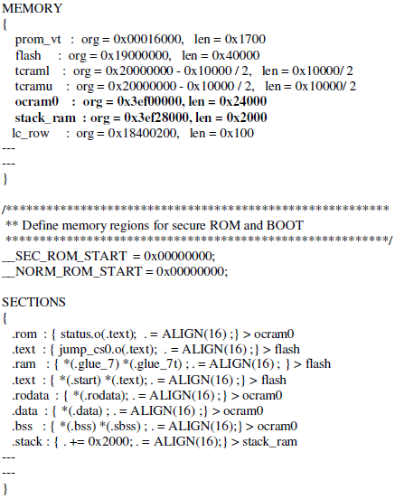
.lnk looks like: (this linker file is of ARM core)

And power PC core ‘s linker file looks like:

The highlighted fields give the information for hex. In the above “ocram0” have locations of sram starting from the address “0x3ef00000” and len is “0x24000” i.e. hex file starting will be “0x3ef00000” and may go upto “starting address+len =3ef24000”.
If the .elf/hex requires more area than the provided in linker file than there will be ERROR “memory out of range” during the make “process of C code”. In that case either optimize the .c file or extend the memory region in linker file.
FILES GENARTED ON SoCs ON RUNNING “.C” files
When a “.c” file runs in SoC setup ,the below files generated for each .c.
*.crt0.o, *.lst , .map, *.o, *.out, *.lnk, *.hex, *.srec
NOTE:* is pattern name like,PATTERN_NAME.hex
Map file and .lst file:
Map files contains the memory allocation details and addresses for each modules. And .lst gives the details for program counter movement for each piece of code and files/functions which are executed.
A symbol table is a look-up between symbol names and their addresses in memory. Compiler normally produces .lst file for the assembly code, and .map file with information about program and data memory usage.
A typical map file looks like: (this is for ARM core based SoCs)

And .lst looks like:

And .srec looks like:

Summary:
In SoC environment, there is lots of module exists and stimulus is generated from .c file. For compiling and executing the whole SoC environment for .c file, make file is required in which the core/processor related switches are provided. Through the C building process, hex file is generated that hex file is loaded in to a desired memory. The starting and end address range for hex file is decided by linker file and entry point for c execution is given in crto file. Finally core/processor , execute this hex file and stimulus is generated corresponding to .c file.
Conclusion and future work:
In SoC setup, Core execute the hex file and stimulus is generated corresponding to what is provided in .c file.In SoC environment, to run at small pattern or .c the whole setup is make and compiled for which the hex file is generated, although the requirement was that to make the hex file of the included and necessary files used for .c make and compile flow. For example, to run the pattern (.c file) which has only one register reading/ writing and print the info, the whole SoC setup will make and compile and hex will generated for that files also, in such hex should have the information of the files which are used in .c building process. This can be taken care by tool/core or some script so that hex file is of the necessary files used in C building process.
References
http://www.tenouk.com/ModuleZ.html
Book: Real-Time Concepts for Embedded Systems(http://www.e-reading.club/book.php?book=102147)
Related Semiconductor IP
- HBM4 PHY IP
- Secure Storage Solution for OTP IP
- Ultra-Low-Power LPDDR3/LPDDR2/DDR3L Combo Subsystem
- MIPI D-PHY and FPD-Link (LVDS) Combinational Transmitter for TSMC 22nm ULP
- VIP for Compute Express Link (CXL)
Related Articles
- Select the Right Microcontroller IP for Your High-Integrity SoCs
- Open-Source Design of Heterogeneous SoCs for AI Acceleration: the PULP Platform Experience
- Top 5 Reasons why CPU is the Best Processor for AI Inference
- Interstellar: Fully Partitioned and Efficient Security Monitoring Hardware Near a Processor Core for Protecting Systems against Attacks on Privileged Software
Latest Articles
- Making Strong Error-Correcting Codes Work Effectively for HBM in AI Inference
- Sensitivity-Aware Mixed-Precision Quantization for ReRAM-based Computing-in-Memory
- ElfCore: A 28nm Neural Processor Enabling Dynamic Structured Sparse Training and Online Self-Supervised Learning with Activity-Dependent Weight Update
- A 14ns-Latency 9Gb/s 0.44mm² 62pJ/b Short-Blocklength LDPC Decoder ASIC in 22FDX
- Pipeline Stage Resolved Timing Characterization of FPGA and ASIC Implementations of a RISC V Processor
