Automated Transistor-Level Optimization in Standard-Cell Based Digital Design
Campbell, CA 95008
Abstract
As feature sizes continue to shrink at a breakneck pace, transistor-level analysis and optimization in digital design is becoming a necessity for achieving a solution with the unique combination of performance, power, and area. Hybrid optimization is a methodology of simultaneously optimizing a digital design at gate, transistor, and physical levels of abstractions, to achieve large performance gains late in the design cycle. Hybrid optimization uses a novel approach to deal with the complexity of a large design while achieving the accuracy of operating at transistor-level. A brief description of hybrid optimization is presented in this paper. Results for several representative industrial designs are presented. These results clearly demonstrate that hybrid optimization enables designers to attain performance targets beyond that achievable by gate-/cell-level optimization tools alone.
Introduction
Digital design automation tools and methodologies have failed to keep pace with the increased ability of fabrication processes to pack tens, or even hundreds of millions of devices on a die. Consequently, the quality of designs created using automated tools has fallen far behind the quality of handcrafted designs [1]. This gap in quality is most visible in the area of performance. While the handcrafted designs are approaching the 5GHz clock speed mark, getting the standard-cell based synthesized designs to work at 500 MHz at state-of-the-art 90nm and 65nm process nodes, remains a serious challenge. This performance gap has led to industry-wide chronic problems in meeting target performance for digital designs, leading to months of slippage late in the design cycle. Heavy manual intervention to achieve the last 50-100 MHz of the target performance, has become commonplace, and manual creation of design-specific tactical cells has become virtually routine for high-performance standard-cell based designs.
A. Performance Gap: Prior Studies
This performance gap between handcrafted custom and standard cell-based synthesized designs have been studied by various researchers [1-4]. As early as mid-1980's, it was
shown that a fixed and limited set of library elements could constitute a major bottleneck in achieving target quality in a synthesized design. More recently, researchers have estimated that as much as 25 percent of the quality gap between automatically created designs, and hand-crafted ones, may be attributable to the fixed set of cells in a pre-defined library that is created for a broad range of possible designs, but are not optimized for the timing context found in any particular design.
B. Hybrid Optimization
Recently, we have developed a unique optimization technique, hybrid optimization, which tunes performance of digital designs at gate/cell level, physical level, and transistor level of abstraction in a unified, fully automated framework [5]. This technology is embedded in Zenasis Technologies’ flagship timing optimization product, ZenTime. A particularly unique feature of hybrid optimization is its ability to harness the power of a variety of transistor-level optimization techniques, which include coarse-grain sizing, continuous sizing, beta ratio variation, culminating in creation of custom standard cells on-the-fly during optimization. All these are done while remaining within the established standard-cell based design flow.
This paper begins with a brief overview of the hybrid optimization technology. Next, the paper presents performance improvement results from application of this hybrid optimization technology to several industrial designs ranging in size from 30,000 gate equivalents to approximately 300,000 gate equivalents. The results show hybrid optimization achieving significant performance improvements in the range of 10%-18% at a late stage, which is very difficult to achieve using any other design-oriented approach without impacting the schedule.
Hybrid Optimization In a Nutshell
Transistor-level improvements in hybrid optimization include the full range of custom design techniques that can be applied to a design already technology-mapped to a given cell library. These include (i) discrete (coarse-grain) sizing of existing standard cells to create new drive strengths or new rise-fall characteristics, (ii) continuous sizing of existing standard cells given specific context of use in a design to provide the highest performance locally in the design, (iii) continuous sizing of groups of existing standard cells, given the specific context of use in a design, and (iv) creation of custom transistor topologies as well as sizing of transistors for that topology, to yield new cells that best improve the timing of the critical region in a given design [5].
The results of hybrid optimization are encapsulated in new transistor-level blocks that are fully compatible with any given standard-cell architecture. Consequently, from a digital designer's perspective, hybrid optimization constitutes a relatively straightforward extension to the familiar standard-cell based design flow. Figure 1 depicts the various phases in a typical design flow where hybrid optimization can be used to improve a given design. Since hybrid optimization can account for the physical view of a design, it can be used as late as post-clock-tree-synthesis (post-CTS), although the benefits are expected to be the greatest when it is applied as early as possible.
An overall view of the hybrid optimization process is presented in Figure 2. The key steps in hybrid optimization are clustering and mapping. Clustering, which is driven by timing and physical design information, is used to determine groups of cells, the timing characteristics of which can be improved by transistor-level optimization. Mapping is used to create an optimal (or near-optimal) transistor-level implementation of a cluster, given its context – timing, loading, physical placement relative to other cells in the design, etc.
Figure 3 illustrates the large local improvements possible in hybrid optimization due to its ability to custom-craft blocks of logic to best improve the timing context in the critical region of a given design. In this example, hybrid optimization successfully uses transistor-level design techniques to achieve greater than 60 percent local improvement in delay through a block of logic, while reducing transistor count by 41 percent, and eliminating 2 uncharacterized interconnect wires between standard cells in the original block of logic.
Experimental Setup and Results
The benefits of ZenTime are illustrated with the results for five performance-critical industrial design blocks ranging in size from approximately 7000 instances (~30,000 gates equivalent) to approximately 80,000 instances (~320,000 gates equivalent). Original performance of these circuits, measured in clock frequency, range from 167 MHz to 339 MHz. In each case, the designs were optimized aggressively using commercial design tools, to establish a baseline design. The designs were then imported into ZenTime and optimized further.
Summary of important characteristics of the designs, including the size of the timing-critical portion of the design, is shown in Table 1. DC is Synopsys’ Design Compiler. Ambit, PKS, and SE (SOC Encounter) are tools from Cadence. A schematic view of the interfaces to ZenTime is shown in Figure 4, while design flows for the original design, and the data formats used to transfer the designs between established standard-cell based design flows and ZenTime, are summarized in Table 2. The results of performance improvement using ZenTime are summarized in Table 3, which also shows the runtime on a Solaris server with a 900 MHz CPU, rounded to the nearest hour. In each case, performance improvement, measured in terms of clock frequency enhancement, lies in the range of 20 MHz to 60 MHz (10% to 18% relative to original clock frequency), and was verified by commercial timing tools. Usage of new cells, beyond what was originally available in the starndard-cell library, and change in instance count due to Zentime optimization, is summarized in Table 4.
An important aspect of ZenTime optimization is revealed by a comparison of slack distribution in the pre-ZenTime optimized design to that in the post-ZenTime optimized design: this is shown in Figures 5(a) through (e). Standard –cell-based designs created using automated tools typically get stuck on a relatively small number of critical paths, resulting in a broad distribution of slacks throughout the design. This is also evident from the "pre-optimization" slack distribution plots in Figures 5(a) through (e). For all the selected designs, optimization in ZenTime caused the slack distribution to tighten, with the worst slack improving significantly and the peak in the distribution moving higher. In other words, the designs got tighter because of ZenTime optimization.
Conclusions
Results from optimization of several industrial circuits using the new hybrid optimization technique, clearly establish the power of this methodology. Performance improvements of 30 to 70 MHz were achieved in all cases.
Since hybrid optimization does not change the flow of any standard cell-based design methodology, it is very easily applicable in any such flow. Due to its ability to optimize designs at the transistor level, hybrid optimization holds the promise to improve other key quality metrics for designs like power.
References
-
Chinnery, D.G., and Keutzer, K., "Closing the Gap Between ASIC and Custom: An ASIC Perspective," Proc. Des. Autom. Conf., 2000, pp. 637-642.
-
Dally, W.J., and Chang, A., "The Role of Custom Design in ASIC Chips," Proc. Des. Autom. Conf., 2000, pp. 643-647.
-
Hill, D., "Sc2: A Hybrid Automatic Layout System," Proc. Int'l. Conf. on Comp.-Aided Des., 1985, pp. 172-174.
-
Keutzer, K., Kolwicz, K., and Lega, M., "Impact of Library Size on Quality of Automated Synthesis," Proc. Int'l. Conf. on Comp.-Aided Des., 1987, pp. 120-123.
-
Bhattacharya, D., and Boppana, V., "Design Optimization with Automated Flex-Cell Creation," in Closing the Gap Between ASIC & Custom, Norwell, MA: Kluwer Academic Publishers,., 2002, pp. 241-266.
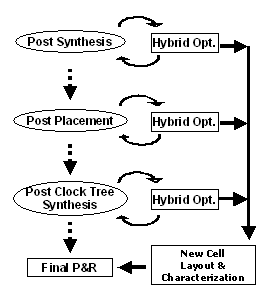
Figure 1: Scenarios for use of hybrid optimization in standard-cell based automated digital design.
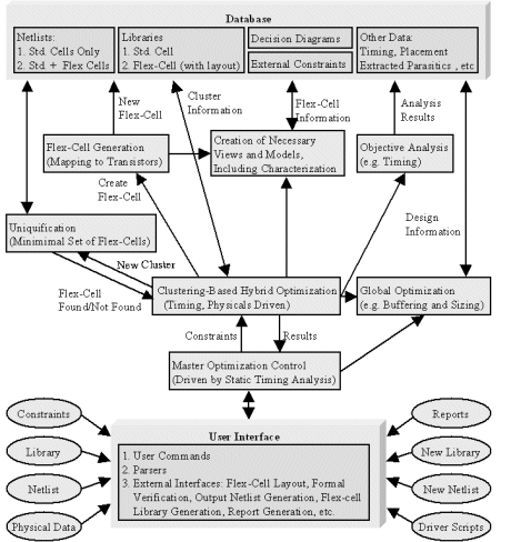
Figure 2: Overall view of hybrid optimization methodology.
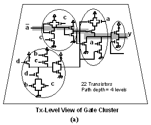
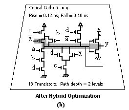
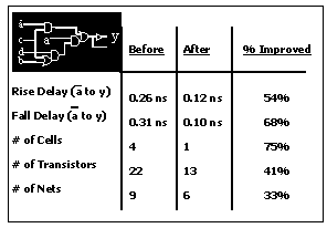
Figure 3: Benefits of hybrid optimization illustrated: (a) Transistor-level view of cluster of standard cells in original design; (b) New complex cell after mapping in hybrid optimization; (c) Comparison of original cluster's characteristics to those of optimized cell.
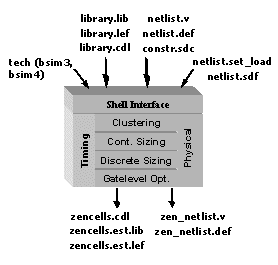
Figure 4: ZenTime input/output interfaces.
| Design | #Standard-Cell Instances | #Instances in Critical Region | Avg. Path Depth |
| CKT1 | 7017 | 5199 | 20 |
| CKT2 | 18265 | 5387 | 20 |
| CKT3 | 33940 | 7581 | 38 |
| CKT4 | 38130 | 10414 | 19 |
| CKT5 | 80277 | 1313 | 20 |
Table 1: Characteristics of selected industrial designs.
| Design | Original Design Flow | Cell Information | Design, Constraints, Timing |
| CKT1 | DC w/ wireload | .lib, .cdl | .v, .sdc |
| CKT2 | Ambit w/ wireload | .lib, .cdl | .v, .sdc |
| CKT3 | PKS w/ physicals | .lib,.lef, .cdl | .v, .def, .sdc, .sdf |
| CKT4 | DC, SE | .lib, .lef, .cdl | .v, .def, .sdc, .sdf |
| CKT5 | PKS w/ physicals | .lib, .lef, .cdl | .v, .def, .sdc, .sdf |
Table 2: Flow and interface information for selected designs.
| Design | Initial Clock Freq. (MHz) | Final Clock Freq. (MHz.) | Improvement in Performance | Run Time (hrs) |
| CKT1 | 339 | 400 | 18% | 5 |
| CKT2 | 167 | 193 | 16% | 8 |
| CKT3 | 187 | 219 | 18% | 33 |
| CKT4 | 297 | 345 | 16% | 35 |
| CKT5 | 188 | 206 | 10% | 5 |
Table 3: Performance improvement summary for selected industrial circuits, due to hybrid optimization, and corresponding run times.
| Design | Total number of instances (Initial) | Number of Unique ZenCells (added) | Total number of ZenCell instances (added) | Total number of instances (final) |
| CKT1 | 7017 | 96 | 500 | 6951 |
| CKT2 | 18265 | 49 | 183 | 18275 |
| CKT3 | 33940 | 165 | 3821 | 34389 |
| CKT4 | 38310 | 132 | 5927 | 36192 |
| CKT5 | 80277 | 80 | 640 | 78639 |
Table 4: Change in instance count due to ZenTime optimization.
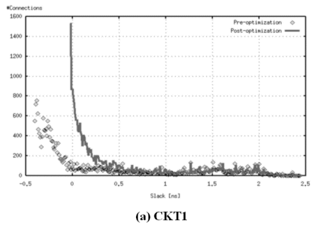
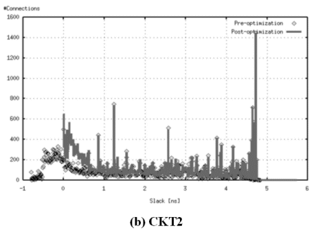
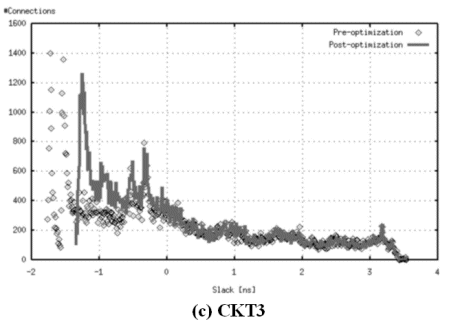
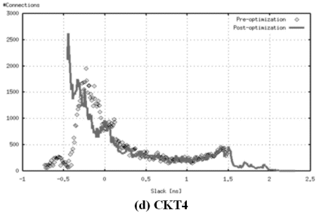
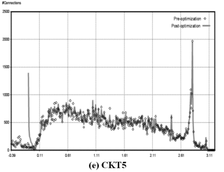
Figure 5: Slack distributions after ZenTime optimization
Related Semiconductor IP
- Wi-Fi 7(be) RF Transceiver IP in TSMC 22nm
- PUF FPGA-Xilinx Premium with key wrap
- ASIL-B Ready PUF Hardware Premium with key wrap and certification support
- ASIL-B Ready PUF Hardware Base
- PUF Software Premium with key wrap and certification support
Related White Papers
- Design patterns in SystemVerilog OOP for UVM verification
- Functional Safety in Road Vehicles
- It's Just a Jump to the Left, Right? Shift Left in IC Design Enablement
- Towards Activity Based System Level Power Estimation
Latest White Papers
- Boosting RISC-V SoC performance for AI and ML applications
- e-GPU: An Open-Source and Configurable RISC-V Graphic Processing Unit for TinyAI Applications
- How to design secure SoCs, Part II: Key Management
- Seven Key Advantages of Implementing eFPGA with Soft IP vs. Hard IP
- Hardware vs. Software Implementation of Warp-Level Features in Vortex RISC-V GPU