The Arasan I3C Secondary Controller IP Core implements Active controller functionality as defined by the MIPI Alliance’s I3C Specification and Secondary Controller logic. The I3C bus is used for various sensors in the mobile/automotive system where the active controller transfers data and control between itself and various sensor devices. In some applications, the active controllers can handoff the controller role to the secondary controller on the bus. The Dual role IP joins the I3C bus as a secondary controller (as a target) and will request/accept the controller role. The IP core provides a 32bit AHB bus as application interface to configure and control the transfers. The controller manages the control signal to IO buffers during the active and standby mode. Please note that the User needs to provide appropriate IO buffers to meet the I3C specification.
The I3C Dual Controller implements support for legacy I2C Slave devices, Clock frequency scaling, Open-drain and Push-pull operation of I3C Interface, and Dynamic Addressing support. The I3C Dual Controller supports the required SDR mode with Clock frequency of up to 12.5 MHz and also the HDR mode (HDR-DDR) as defined by the I3C Specification.
I3C Dual Controller
Overview
Key Features
- Compliant with MIPI I3C Specification (v1.1/v1.1.1)
- Compliant with MIPI I3C HCI Specification (v1.2)
- Supports up to 12.5 MHz operation using Push-Pull
- Open-Drain and Push-pull type transactions
- Supports legacy I2C devices
- Dynamic Addressing while supporting Static Addressing for Legacy I2C devices
- Legacy I2C Messaging
- I2C-like Single Data Rate Messaging (SDR)
- High Data Rate Messaging Modes (HDR-DDR, HDR-TSP, HDR-TSL)
- Reception of In-band Interrupt support from the I3C Slave devices
- Reception of Hot-Join from newly added I3C Slave devices
- Support Target reset
- Support Group Addressing
- Support for JESD403-1 Sideband Interface
- Synchronous Timing Support and Asynchronous Time Stamping
- AHB System Bus
- Slave Interface for configuration and PIO mode
- Master Interface for DMA mode
- Support for up-to Eight rings in DMA mode and configurable as per the application requirement
- Configurable FIFO for transferring data between Master and the Slave devices
- Register based array for
- Command Queue
- Response Queue
- IBI Data Queue
- IBI Response descriptor
- Receive Data Buffer
- Transmit Buffer
- Common buffer usage for both PIO/DMA mode
Benefits
- Capability to hot join the I3C bus with secondary controller logic
- Support for simple controller role request for the purpose of requesting or attempting to regain the controller role from the active controller
- Autonomously service certain standard CCCs sent by the active controller
- Standby controller mode specific register set for configuration and control via Extended capability register
- Optional support for generic read-type and write-type transactions sent by the active controller
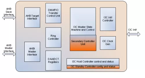
Block Diagram
Deliverables
- RMM compliant synthesizable RTL design in Verilog
- Easy-to-use Test environment
- Synthesis scripts
- Technical documents
- Validated with 3rd Party VIP and available as an additional option
Technical Specifications
Maturity
Silicon proven
Availability
NOW