Overview
A Finite Impulse Response (FIR) filter performs a convolution of an input data sequence with the filter's impulse response (the discrete-time inverse Fourier transform of its desired frequency response), which is stored in memory. The equation for performing the convolution is given by
where yn is the filter output at sample n, xn-i is the value of the filter input i samples in the past, and hi is the ith value of the filter impulse response.
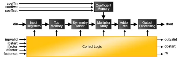
The Lattice FIR (Finite Impulse Response) Filter IP core is a widely configurable, multi-channel FIR filter, implemented using high performance sysDSP™ blocks available in Lattice devices. In addition to single rate filters, the IP core also supports a range of polyphase decimation and interpolation filters. The utilization versus throughput trade-off can be controlled by specifying the number of multipliers used for implementing the filter. The FIR Filter IP core supports as high as 256 channels, with each having up to 2048 taps. The input data, coefficient and output data widths are configurable over a wide range. The IP core uses full internal precision while allowing variable output precision with several choices for saturation and rounding. The coefficients of the filter can be specified at generation time and/or re-loadable during run-time through input ports.
High Performance ECP3 DSP Based Filter Designs
Lattice has developed the following Reference Designs to highlight the powerful DSP capability of the LatticeECP3 FPGA.
* Direct Form 64-Tap FIR Filter: In the direct form FIR filter, the input samples are shifted into a shift register queue and each shift register is connected to a multiplier. The products from the multipliers are added together to get the FIR filter’s output sample. This example shows a 64-tap FIR filter using 16 sysDSP blocks and approximately 512 slices in the LatticeECP3 FPGA.
* 128-Tap Long Asymmetrical Filters Using Ladder Architecture: Using the ladder architecture, the FIR filter is split into sections each having the same coefficient set as if it was a single continuous filter chain. Instead of connecting the shifted data and the result outputs from the first section to the corresponding input of the next section, the ladder network connects a delayed version of the first stage input data to the second stage input data and sums a delayed version of the first stage sum output with the second stage sum output.
* 256-Tap Long Symmetrical Filters Using Ladder Architecture: The impulse response for most FIR filters is symmetric. This symmetry can generally be exploited to reduce the arithmetic requirements and produce area-efficient filter realizations. It is possible to use only half the multipliers for symmetric coefficients compared to that used for a similar filter with non-symmetric coefficients. An implementation for symmetric coefficients is shown in the figure below. The 256-tap long symmetrical filter example uses only 32 sysDSP slices, 2EBR and 3.5K slices.
* Polyphase Interpolator FIR Filter Designs: The polyphase interpolation filter implements the computationally efficient 1-to-P interpolation filter where P is an integer greater than 1. The example below shows a design with an interpolation by 16 that uses 128 taps. This requires 8 polyphase filters (sub-filters) with 16 coefficients each.
Learn more about Filters Transforms IP core
Processor Architecture for High Performance Video Decode
No size fits all for signal processing on FPGA (RF Engines)
Employing general-purpose processors for radio DSP
Finally a Practical ''Do and Don't'' primer on architecting FPGA solutions for DSP design. With more do's than don’ts, the article is a down-to-basics look at how to avoid the pitfalls and realize device benefits
Regardless of whether you are using VHDL, System Verilog, or a different design capture language, there are a number of universal design techniques with which FPGA engineers should be familiar, from the very simple to the most advanced.
The real results of a double-precision matrix multiply core that can easily be extended to a full DGEMM benchmark are demonstrated.