A2B is a high performance System-on-Chip interconnect designed for use in synthesizable designs. It is specifically developed to meet the challenges of multiprocessor and multiple DMA / IO processor designs. A2B is designed to have the highest possible occupancy so that the sustainable bus bandwidth closely approaches the available peak bandwidth of a given configuration.
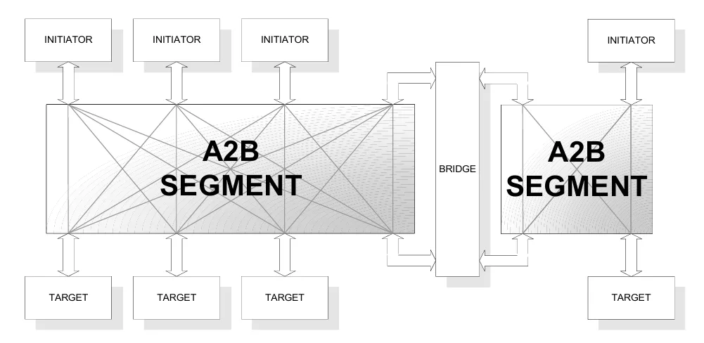
A2B is a fully synchronous system that is user configurable to provide a wide variety of performances to best match the system level requirements of a particular implementation. The user (system architect) can configure the system for address and data widths, may add special bus fields to transfer custom information and may select the arbitration algorithm and Quailty-of-Service (QoS) methodology. Bridges can also be included to allow different bus widths in separate sections so that a variety of devices can connect together. This allows, for example, a collection of CPUs to have a very wide data connection to system memory and for slower I/O devices to have a narrower data connecting through the bridge to the system memory. Bridges may also be used as a nexus building block for Network-on Chip applications as well as interfaces to blocks that use other interconnect protocols.
SYSTEM INTERFACES
A2B is a designed with it's own native protocol for the highest performance System-on-Chip interconnect. However, interface veneers can be supplied to attach the industry standard interfaces such as OCP, AMBA-AXI, Wishbone etc. A2B is meant to provide a mechanism for all high-speed communications within an S0C and as such also allows for point-to-point connections that provide fixed bandwidth and fixed latency between modules. The bridge protocol also allows for split bridges that have a “long distance” span between them. Through this mechanism it also possible to connect multiple chips together if necessary.
CONFIGURATION
The A2B is configurable to generate a wide variety of topologies to best suit an individual application. The configuration is table-driven and an appropriate hierarchy is built so that the interconnection fabric exists on the upper layers of the system hierarchy and the TAP modules reside in the modules that they interface to. The resulting bus structure will also have a companion testbench and verification suite that allows the incremental addition of user modules to build a complete system.