UCIe IP
UCIe IP Cores (Universal Chiplet Interconnect Express) facilitate high-bandwidth communication between heterogeneous chiplets, in a single package.
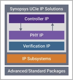
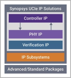
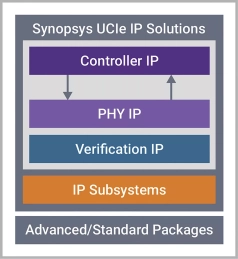
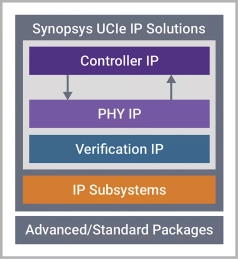
The UCIe™ physical layer includes the link initialization, training, power management states, lane mapping, lane reversal, and scrambling. The UCIe™ controller includes the die-to-die adapter layer and the protocol layer. The adapter layer ensures reliable transfer through link state management and parameter negotiation of the protocol and flit formats. The UCIe™ architecture supports multiple standard protocols such as PCIe, CXL and streaming raw mode.
Explore our vast directory of UCIe IP Cores below.
All offers in
UCIe IP
Filter
Compare
55
UCIe IP
from
19
vendors
(1
-
10)
-
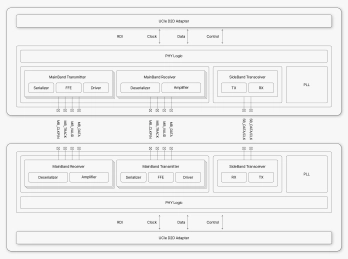
UCIe PHY (Die-to-Die) IP
- Compliant with UCIe v2.0, supporting 4/8/12/16/24/32GT/s data rates
- for Standard Package up to 16 lanes / for Advanced Package up to 64 lanes
- Provides a 1024-bit data bus width with high-throughput die-to-die communication
- Includes automatic per-lane calibration and optional transmitter de-emphasis
-
-
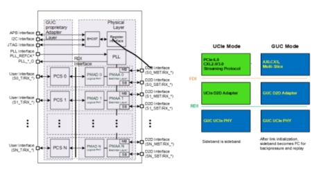
TSMC CLN5FF GUCIe LP Die-to-Die PHY
- IGAD2DY11A is an LP (Low Power) Die-to-Die (D2D) PHY for SoIC-X Face-to-Face advanced package.
- This GUCIe PHY not only supports UCIe specification rev 1.1 compliance physical layer and Raw D2D interface (RDI) but also optionally provides the
-
UCIe Controller baseline for Streaming Protocols for ASIL B Compliant, AEC-Q100 Grade 2
- UCIe Controller baseline for Streaming Protocols for ASIL B Compliant, AEC-Q100 Grade 2
- Low latency controller for UCIe-based multi-die designs
- Includes Die-to-Die Adapter layer and Protocol layer
-
-
-
UCIe Controller baseline for Streaming Protocols
- Low latency controller for UCIe-based multi-die designs
- Includes Die-to-Die Adapter layer and Protocol layer
- Supports on-chip interconnect fabrics including AXI, CHI C2C, CXS, PCIe, CXL, and streaming
- Error detection and correction with optional CRC and retry functionality
-
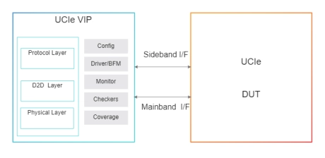
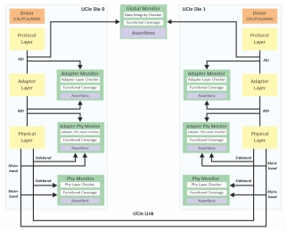
UCIe 2.0 Verification IP
- Available in native SystemVerilog (UVM/OVM /VMM) and Verilog.
- Unique development methodology to ensure highest levels of quality.
- Availability of various Regression Test Suites.
- 24X5 customer support.
-
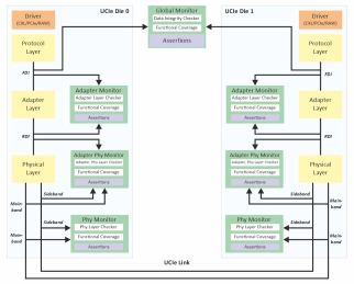
UCIe Verification IP
- Available in native SystemVerilog (UVM/OVM /VMM) and Verilog.
- Unique development methodology to ensure highest levels of quality.
- Availability of various Regression Test Suites.
- 24X5 customer support.
-
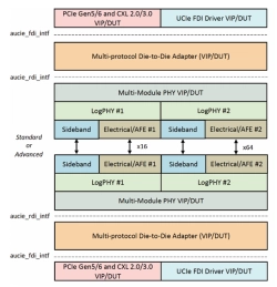
Verification IP for UCIe
- Avery UCIe VIP provides a comprehensive verification solution featuring an advanced UVM environment that incorporates constrained random traffic gener ation, robust D2D and LogPHY layer controls and error injection, protocol checks and coverage, functional coverage, protocol analyzer-like features for debug ging, and performance analysis metrics.
- PCIe/CXL VIP supports FDI/RDI adapters for complete stack verification. With the advanced capabilities of Avery VIP, engineers can work more efficiently, develop more complex tests, and work on more complex topologies, such as bifurcation.
