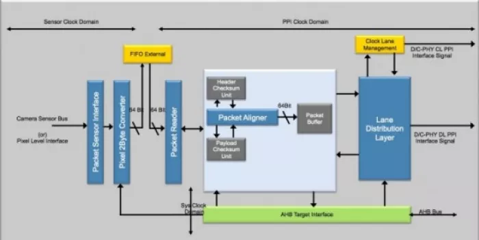
The MIPI Camera Serial Interface (CSI-2) Transmitter, typically resides in a mobile platform’s camera module, and communicates over a D-PHY/C-PHY link to a CSI-2 Receiver in the application processor. The Arasan CSI-2 combo IP is MIPI compliant and provides a standard, scalable, low-power, high-speed interface that supports a wide range of higher image resolutions.
Compliant with the following MIPI specifications
mipi_CSI-2_specification_v1-3
mipi_D-PHY_specification_v1-2
mipi_C-PHY_specification_v1-1
Pixel Data received from over the Camera Sensor Bus is packed into bytes by the Transmitter IP. The packing of the pixel into bytes follows the CSI-2 spec and based on the pixel format support. This IP calculated and appends an ECC/CRC value to a short packet (or) to the header of a long packet. Selection of ECC/CRC to the header is done based on the PHY connected. For the payload of a long packet carrying pixel data, this IP calculates its CRC value and appends to the packet as a Packet Footer (PF). The packet is buffered in a FIFO and sent to one or more D-PHY/C-PHY depending on the lane distribution scheme set by the camera sensor/user.
MIPI CSI-2 Tansmitter v 1.3, C-PHY compatible
Overview
Key Features
- Use of either D-PHY/C-PHY by user configuration
- • Lane is configurable depending on the bandwidth requirements of the application, up to 8-lanes for DPHY and up to 3-lanes for C-PHY
- • Connectivity to DPHY/CPHY through MIPI PPI Interface
- • High Speed (HS) transmit rates of 182Mbps to 5714Mbps per lane with C-PHY interface
- • High Speed (HS) transmit rates of 40Mbps to 2500Mbps per lane with D-PHY interface
- • Supports for Ultra Low Power Mode (ULPS)
- • Support for Continuous and Non-Continuous Clock Mode
- • Pixel formats supported
- o RAW data type
- o YUV data type
- o RGB data type
- o All user Defined data types / JPEG
- o Generic 8-bit long packet data types
- • Supports Data Type Interleaving
- • Supports Virtual Channel Interleaving
- • Pixel Level Input Interface for Image Sensor
- • Supports Header and Payload Checksum
- • Configurable for two mode of operation
- • Store and Forward Mode – Stores the full pixel packet before forwarding.
- • Cut through Mode – Initiates the HS transmission to D/CPHY as soon as the pixel information is received. Makes use of very shallow memory.
- • Supports Multi Pixel Mode – Multiple Pixels per clock to bring down the sensor clock frequency to support higher resolution applications
- • PPI Data Lane swapping as per user configuration
- • Optional support for Compressed data formats
- • Host interface for register configuration and monitoring,
- • Used for programming both CSI-2 and PHY related registers. Reserved address space [0x00 – 0x0F] for the PHY related registers.
- • Optional support for the AHB/APB Interface
Benefits
- Fully compliant to MIPI standard
- Small footprint
- Code validated with Spyglass
- Functionality ensured with comprehensive verification
- Product quality proven with silicon
- Premier direct support from Arasan IP core designers
Block Diagram

Deliverables
- • Verilog HDL of the IP core
- • User guide
- • Synthesis scripts
- • Lint report
- • CDC report
- • Verilog test suite
- • Gate count estimation available upon request
Technical Specifications
Maturity
In Production
Availability
Now
Related IPs
- MIPI CSI-2 controller Receiver v 2.1, Compatible with MIPI C-PHY v1.2 & DPHY v2.1.
- MIPI CSI DSI Controller - CPHY CSI-2 Transmitter v 2.1, Compatible with MIPI C-PHY v1.2 & DPHY v2.1.
- MIPI CSI-2 Receiver v2.0 Controller IP, Compatible with MIPI C-PHY & D-PHY
- MIPI CSI-2 Receiver v1.1 Controller IP, Compatible with MIPI C-PHY & D-PHY
- MIPI CSI-2 Receiver v1.3 Controller IP, Compatible with MIPI C-PHY & D-PHY
- MIPI CSI-2 with C-PHY Verification IP