Finite Impulse Response IP
Welcome to the ultimate Finite Impulse Response IP hub! Explore our vast directory of Finite Impulse Response IP
All offers in
Finite Impulse Response IP
Filter
Compare
18
Finite Impulse Response IP
from 10 vendors
(1
-
10)
-
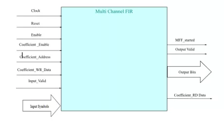
Multi Channel FIR Filter
- Multi Channel FIR filter
- Selectable data and coefficient widths
- Selectable number of data channels
- Selectable number of filter taps
-
ASIP-2
- Platform to design Application Specific Instruction Set Processors (ASIPs).
- Ideal for supporting multi-standard systems.
- Supports a wide range of complex DSP functions.
- The ASIP2 performs Fast Fourier Transform (FFT) to convert time domain signals to frequency domain signals for further processing. It supports FFT sizes from 4 to 8K.
-
ASIP-1
- Platform to design Application Specific Instruction Set Processors (ASIPs).
- Ideal for supporting multi-standard systems.
- Supports a wide range of complex DSP functions .
- The ASIP1 supports the implementation of multiple DSP functions such as Kalman filtering suitable for IQ mismatch.and Finite and Infinite Impulse Response filtering with higher filter order.
-
Ultra-speed FIR Filter
- Systolic array for speed and scalability
- Configurable coefficients
- Configurable data width
- Configurable number of taps
-
Serial FIR Filter
- Serial Arithmetic for Reduced Resource Utilization
- Variable Number of Taps up to 64
- Data and Coefficients up to 32 Bits
- Output Size Consistent with Data Size
-
Parallel FIR Filter
- Variable number of taps up to 64
- Data and coefficients up to 32 bits
- Output size consistent with data size
- Zero-latency operation

-
FIR Filter Generator
- Direct Form 64-Tap FIR Filter: In the direct form FIR filter, the input samples are shifted into a shift register queue and each shift register is connected to a multiplier. The products from the multipliers are added together to get the FIR filter’s output sample. This example shows a 64-tap FIR filter using 16 sysDSP blocks and approximately 512 slices in the LatticeECP3 FPGA.
- 128-Tap Long Asymmetrical Filters Using Ladder Architecture: Using the ladder architecture, the FIR filter is split into sections each having the same coefficient set as if it was a single continuous filter chain. Instead of connecting the shifted data and the result outputs from the first section to the corresponding input of the next section, the ladder network connects a delayed version of the first stage input data to the second stage input data and sums a delayed version of the first stage sum output with the second stage sum output.
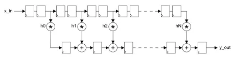
- 256-Tap Long Symmetrical Filters Using Ladder Architecture: The impulse response for most FIR filters is symmetric. This symmetry can generally be exploited to reduce the arithmetic requirements and produce area-efficient filter realizations. It is possible to use only half the multipliers for symmetric coefficients compared to that used for a similar filter with non-symmetric coefficients. An implementation for symmetric coefficients is shown in the figure below. The 256-tap long symmetrical filter example uses only 32 sysDSP slices, 2EBR and 3.5K slices.
- Polyphase Interpolator FIR Filter Designs: The polyphase interpolation filter implements the computationally efficient 1-to-P interpolation filter where P is an integer greater than 1. The example below shows a design with an interpolation by 16 that uses 128 taps. This requires 8 polyphase filters (sub-filters) with 16 coefficients each.
-
DAC Correction Filter
- Efficient, multiplier-free design
- Configurable input and output widths
- Multiple tap-length configurations
-
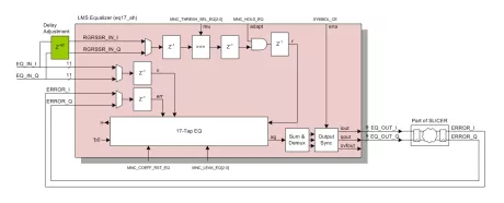
LMS Adaptive Channel Equalizer
- 17-tap T-spaced complex-arithmetic LMS signed-error Channel Equalizer
- Adaptation bandwidth control (mu, step size)
-
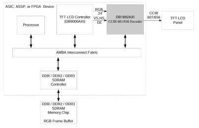
RGB to ITU-R 601/656 Encoder
- The DB1892AXI RGB to CCIR 601 / CCIR 656 Encoder interfaces RGB data along with synchronization signals from a LCD Controller (or any LCD display timing & control unit) to a TFT LCD Panel by-way-of a CCIR 601 / CCIR 656 interface.