Interconnect IP for UMC
-
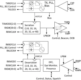
Multiprotocol SerDes PMA
- Supports over 30 protocols including CEI 6G & 11G SR, MR, LR, Ethernet 10GBASE-X/S/K/R, PCIe Gen1/2/3/4, V-by-One HS/US, CPRI, PON, OTN/OTU, 3GSDI, JESD204A/B/C, SATA1-3, XAUI, SGMII
- Programmable (De)Serialization width: 8, 10, 16, 20, 32, or 40 bit
- Tx ring PLL includes fractional multiplication, spread spectrum and Jitter Cleaner function for Sync-E and OTU
- Core-voltage line driver with programmable pre-and post-emphasis
-
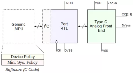
Complete USB Type-C Power Delivery IP
- Mixed signal Analog Front End Macros for 65n, 130n, 150nm, and 180n technologies.
- RTL code from AFE to I2C compatible register set.
- Stand alone C code for Protocol, Device Policy Manager, and System Policy Manager.
- IP demonstration & development board, with compliance reports.
- Full chip integration of USB Type-C, and associated software.
-
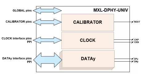
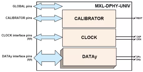
MIPI D-PHY Universal IP in UMC 28HPC+
- Supports MIPI Alliance Specification for D-PHY Version 2.5
- Consists of 1 Clock lane and 4 Data lanes
- Embedded, high performance, and highly programmable PLL
- Supports both low-power mode and high speed mode with integrated SERDES
-
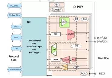
MIPI C-PHY/D-PHY Combo Universal IP in UMC 40LP
- Dual mode PHY can support C-PHY and D-PHY
- Supports MIPI Specification for D-PHY Version 1.2
- Supports MIPI Specification for C-PHY Version 1.0
-
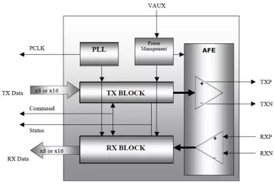
PCI Express PHY serial link PIPE Transceiver IP cell/hard macro
- Supports 2.5Gb/s serial data rate
- Utilizes 8-bit or 16-bit parallel interface to transmit and receive PCI Express data
- Full Support for Auxiliary Power (Vaux) for Energy aware systems like Multi-Port Host Controllers
- Data and clock recovery from serial stream on the PCI Express bus
-
I2C Master Serial Interface Controller
- I2C-compatible interface
- AMBA AXI4-Lite bus
- Standard and custom data rates
- Configurable setup/hold times
-
I2C Master Serial Interface Controller
- I2C-compatible interface
- AMBA APB3 bus
- Standard and custom data rates
- Configurable setup/hold times
-
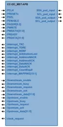
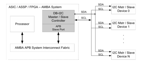
I2C Controller IP- Master / Slave, Parameterized FIFO, APB Bus
-
The Digital Blocks DB-I2C-MS-APB Controller IP Core interfaces a microprocessor via the AMBA APB Bus to an I2C Bus in Standard-Mode (100 Kbit/s) / Fast-Mode (400 Kbit/s) / Fast-Mode Plus (1 Mbit/s) / Hs-Mode (3.4+ Mb/s) / Ultra Fast-Mode (5 mbit/s).
The I2C is a two-wire bidirectional interface standard (SCL is Clock, SDA is Data) for transfer of bytes of information between two or more compliant I2C devices, typically with a microprocessor behind the master controller and one or more slave devices.
The DB-I2C-MS-APB is a Master/Slave I2C Controller that in Master Mode controls the Transmit or Receive of data to or from slave I2C devices while in Slave Mode allows an external I2C Master device to control the Transmit or Receive of data.
-
-
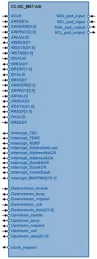
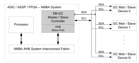
I2C Controller IP- Master / Slave, Parameterized FIFO, AHB Bus
-
The DB-I2C-MS-AHB Controller IP Core interfaces a microprocessor via the AMBA AHB Bus to an I2C Bus in Standard-Mode (100 Kbit/s) / Fast-Mode (400 Kbit/s) / Fast-Mode Plus (1 Mbit/s) / Hs-Mode (3.4+ Mb/s) / Ultra Fast-Mode (5 mbit/s).
The I2C is a two-wire bidirectional interface standard (SCL is Clock, SDA is Data) for transfer of bytes of information between two or more compliant I2C devices, typically with a microprocessor behind the master controller and one or more slave devices.
The DB-I2C-MS-AHB is a Master / Slave I2C Controller that in Master Mode controls the Transmit or Receive of data to or from slave I2C devices while in Slave Mode allows an external I2C Master device to control the Transmit or Receive of data.
-
-
MIPI D-PHY Universal IP in UMC 40LP
- Consists of 1 Clock lane and up to 4 Data lanes
- Supports the MIPI Standard 1.1 for D-PHY
- Supports both high speed and low-power modes