The Alphawave CDPCS IP core is a cutting-edge solution to the 800/400/200G Ethernet application. It supports the Physical Coding Sublayer (PCS) for 64B/66B and type 800/400/200GBASE-R function.
The CDPCS supports 64B/66B encoding for transmission of data and control characters, 256/257B transcoding, FEC calculation, and data distribution to support multiple lanes in the Physical Layer. It includes insertion and extraction points for connection to an OTN layer. This core is suitable for use in switch or interface cards or any application that requires a PCS for 800/400/200GbE. All functions of the CDPCS are compliant with the Ethernet Technology Consortium and IEEE 802.3bs. For a complete Ethernet solution, the CDPCS seamlessly integrates with the Alphawave 800/400/200G MAC (CDMAC) core.
800G/400G/200G Ethernet PCS
Overview
Key Features
- CDPCS TX
- 64B/66B encoding of twenty input lanes
- Idle block removal (to reduce overhead for AM insertion)
- 256/257B transcoding (to reduce overhead for FEC insertion)
- Scrambling (optional bypass)
- Alignment Marker (AM) insertion. Unique marker portion of AM for each lane is s/w configurable.
- Forward Error Correction (FEC) parity calculation and insertion (2x400G/2x200G/2x100G interleaved)
- 800G: Symbol Distribution so that output is composed of 32 logical lanes
- 400G: Symbol Distribution so that output is composed of 16 logical lanes
- 200G: Symbol Distribution so that output is composed of 8 logical lanes
- Test pattern generation (scrambled idles)
- Clause 45 MDIO register set
- Error detection and interrupt reporting
- CDPCS RX
- 800G: Alignment lock and lane deskew of 32 lanes. Unique marker portion of AM for each lane is s/w configurable
- 400G: Alignment lock and lane deskew of 16 lanes. Unique marker portion of AM for each lane is s/w configurable
- 200G: Alignment lock and lane deskew of 8 lanes. Unique marker portion of AM for each lane is s/w configurable
- Lane reordering
- FEC decoding and error correction (2x400G/2x200G/2x100G interleaved)
- Alignment marker removal
- Descrambling (optional bypass)
- Reverse 256/257B transcoding
- 64B/66B decoding to twenty output lanes
- Test pattern monitoring
- Clause 45 MDIO register set
- Error detection and interrupt reporting
- Loopback from TX CDMII to RX CDMII
- Performance Monitoring and Statistics
- Dynamic skew measurement for each lane
- FEC Corrected code word count
- FEC Uncorrected code word count
- Total FEC symbol error counter
- Per lane FEC symbol error counters
- Total Corrected 1s and 0s counters
- FEC histogram: 0-15 Errors per FEC codeword
- FEC degrade SER
- PCS Status – link up/down
- High bit error rate (hi-BER)
- BER counter
- Test pattern error counter
- Multi-lane AM status (locked and aligned/not locked and aligned)
- Lane mapping for each of physical lanes 0-7/0-15
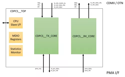
Block Diagram
Applications
- High-density routers for data centres
- Telecom/5G Wireless
- Time-sensitive Networks
- Access Switches