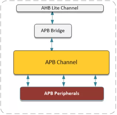
The APB Channel provides the necessary infrastructure to connect as many as 16 AHB Slaves (numbered 0-15) to an APB Bus Master. The APB Channel performs a combinational decode on the incoming APB address to produce the block selects for the various APB Slaves.
Typically, the APB Channel is connected as in the following description. Each of the APB Channel’s 16 Mirrored Slave Ports is connected to an APB Slave module (e.g. Timer, UART, GPIO). On the Master side, the APB Channel’s Mirrored Master Port typically is connected to an AHB to APB Bridge module.
APB Channel with Decoder and Data Mux
Overview
Key Features
- AMBA® APB 2.0 and 3.0 Compatible
- Bus Infrastructure for up to 16 APB Slaves
- Includes address decode
- Includes read data muxing
Block Diagram
Deliverables
- Verilog Source
- Complete Test Environment
- AHB Bus Functional Model
- C Sample Code
Technical Specifications
Maturity
Silicon Proven
Availability
Now
Related IPs
- AHB Channel with Decoder and Data Mux
- High performance 8-bit micro-controller with 256 bytes on-chip Data RAM, three 16-bit timer/counters, and two 16-bit dptr; 0.25um UMC Logic process.
- Clock and Data Recovery of HDB3/B3ZS coded signals
- 2D (vector graphics) & 3D GPU IP A GPU IP combining 3D and 2D rendering features with high performance, low power consumption, and minimum CPU load
- LDPC Decoder and Encoder that supports DVB-S2 DVB-S2X DVB-T2 DVB-C2 CMMB DMB-T
- ISO/IEC 7816-3 digital controller for interface device compliant with ETSI TS 102 221 and EMV 2000 standards