A Unified CPU Model for SOC Verification
By Ravikumar Avudai Nayagam, HCL Technologies
Chennai, India
Abstract:
Today’s System-on-Chip (SOC) verification becomes more challenging as more complex functionalities like network processor, security processor and other complex chips are getting into SOC. The verification of those devices for its functionality demands complex software applications, to be developed in the test bench environment. Verification of the SOC by system level, by using the model supplied by the vendors, is cumbersome since the models provided by the vendors are primitive and is difficult to develop the system level task calls using those primitive models. It will be possible to use the processor net-list with the code memory model for specific tasks, which is normally very slow for system level testing.
Introduction
In this paper, the necessity for a methodology for CPU modeling which paves the way for system level testing is presented. A multi-layer approach for the model is proposed so that these layers can be standardized and shared among the SOC community.
The multi-layer abstraction is provided below. Figure 1shows the different layers of a CPU model.
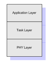
Figure 1: Layers of CPU model
PHY Layer
The PHY layer models the I/O signal characteristics of the CPU data plane and the control plane. It provides the service for the following primitive commands.
Table 1 shows the values of the different fields for various commands. The command set shall be expanded as per the needs.
Task Scheduling Layer
It provides the container for task flow for periodic time ticks and container for task flows for asynchronous events (interrupt container).
Task container can be of three types,
Foreground task holds the tasks of different time slices
For every 10 ms tick, the tasks in the 10 ms container will get executed and for every 50 ms the 50 ms container will get executed and for every 100 ms, the 100 ms container will get executed.
Table 1: Commands and their fields
Background Task Container
The background task will get executed in a loop after the CPU has finished the foreground task.
Interrupt Container
Interrupt tasks are handled in the container. There is a configuration layer pertaining to the interrupt tasks. The configuration layer is programmed according to the target CPU.
Figure 2 provides the task flow with the system time.
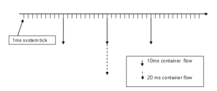
Figure 2: Task flow with system time
Application Layer
Here the tasks are written in higher abstraction.
There has to be a utility which provides the template for the verification engineer to develop the test cases in system level. This utility compiles and provides the primitive calls which are threaded in the container and the cycles are generated by the PHY layer.
Figure 3 explains the layer approach and the necessity for a utility to standardize the output which can be easily understood by the PHY layer of the different processors.
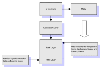
Figure 3: Tool flow
Limitations
The unified model approach is portable across different CPU PHY layers and is fast. It also helps to verify the SOC in system level. However it is an approximation model which helps to validate the different peripherals, this cannot be treated as a cycle-by-cycle match of CPU core.
Chennai, India
Abstract:
Today’s System-on-Chip (SOC) verification becomes more challenging as more complex functionalities like network processor, security processor and other complex chips are getting into SOC. The verification of those devices for its functionality demands complex software applications, to be developed in the test bench environment. Verification of the SOC by system level, by using the model supplied by the vendors, is cumbersome since the models provided by the vendors are primitive and is difficult to develop the system level task calls using those primitive models. It will be possible to use the processor net-list with the code memory model for specific tasks, which is normally very slow for system level testing.
Introduction
In this paper, the necessity for a methodology for CPU modeling which paves the way for system level testing is presented. A multi-layer approach for the model is proposed so that these layers can be standardized and shared among the SOC community.
The multi-layer abstraction is provided below. Figure 1shows the different layers of a CPU model.
Figure 1: Layers of CPU model
PHY Layer
The PHY layer models the I/O signal characteristics of the CPU data plane and the control plane. It provides the service for the following primitive commands.
- Memory write,
- Memory read, and
- Idle cycle
{
Byte Command length [7:0],
Byte Command Id [7:0],
lword Parameter[63;0]
lword Data[63:0]
}
Byte Command length [7:0],
Byte Command Id [7:0],
lword Parameter[63;0]
lword Data[63:0]
}
Table 1 shows the values of the different fields for various commands. The command set shall be expanded as per the needs.
Task Scheduling Layer
It provides the container for task flow for periodic time ticks and container for task flows for asynchronous events (interrupt container).
Task container can be of three types,
- Foreground Tasks
- Background Tasks
- Interrupt Tasks
Foreground task holds the tasks of different time slices
- 10 ms container
- 50 ms container
- 100 ms container
For every 10 ms tick, the tasks in the 10 ms container will get executed and for every 50 ms the 50 ms container will get executed and for every 100 ms, the 100 ms container will get executed.
Table 1: Commands and their fields
| Command ID (1 byte) | Parameter | Data | Command Description |
| 01 | Start address -4 bytes for 32-bit address -8 bytes for 64-bit address | 8 bytes for 64-bit data | Byte Write – Writes the least significant byte in the specified address |
| 02 | Start address -4 bytes for 32-bit address -8 bytes for 64-bit address | 8 bytes for 64-bit data | Word Write – Writes the least significant word the specified address |
| 03 | Start address -4 bytes for 32-bit address -8 bytes for 64-bit address | 8 bytes for 64-bit data | Word Write – Writes the least significant doubleword the specified address |
| 04 | Start address -4 bytes for 32-bit address -8 bytes for 64-bit address | 8 bytes for 64-bit data | Word Write – Writes the long word at the specified address |
| 11 | Start address -4 bytes for 32-bit address -8 bytes for 64-bit address | Byte Read from the specified location | |
| 12 | Start address -4 bytes for 32-bit address -8 bytes for 64-bit address | Word read from the specified location | |
| 13 | Start address -4 bytes for 32-bit address -8 bytes for 64-bit address | Double word read from the specified location | |
| 14 | Start address -4 bytes for 32-bit address -8 bytes for 64-bit address | Long word read from the specified location | |
| 20 | No of CPU clocks, where CPU Bus idles DDDDDDDDh | Idle for Clocks DDDDDDDDh |
Background Task Container
The background task will get executed in a loop after the CPU has finished the foreground task.
Interrupt Container
Interrupt tasks are handled in the container. There is a configuration layer pertaining to the interrupt tasks. The configuration layer is programmed according to the target CPU.
Figure 2 provides the task flow with the system time.
Figure 2: Task flow with system time
Application Layer
Here the tasks are written in higher abstraction.
There has to be a utility which provides the template for the verification engineer to develop the test cases in system level. This utility compiles and provides the primitive calls which are threaded in the container and the cycles are generated by the PHY layer.
Figure 3 explains the layer approach and the necessity for a utility to standardize the output which can be easily understood by the PHY layer of the different processors.
Figure 3: Tool flow
Limitations
The unified model approach is portable across different CPU PHY layers and is fast. It also helps to verify the SOC in system level. However it is an approximation model which helps to validate the different peripherals, this cannot be treated as a cycle-by-cycle match of CPU core.
Related Semiconductor IP
- nQrux® Root of Trust IP
- AXI to UCIe Bridge IP
- UCIe 2.x Controller IP
- SWI3S (SoundWire I3S Interface) Peripheral Controller Core IP
- OpenTitan-based RISC-V Secure Element
Related Articles
- Transactor vs CPU in SoC Verification
- A Survey on SoC Security Verification Methods at the Pre-silicon Stage
- FeNN-DMA: A RISC-V SoC for SNN acceleration
- Veri-Sure: A Contract-Aware Multi-Agent Framework with Temporal Tracing and Formal Verification for Correct RTL Code Generation
Latest Articles
- A Secure dToF LiDAR SoC with Dual-Domain Fingerprinting and Event-Driven AFE Circuit Achieving Sensor-Level Attack Resilience
- ZTA-Q: an Open-source RISC-V Platform for Accurate Quantized CNN Inference
- Automated Pre-Silicon Verification of High-Speed DDR5 and LPDDR5/6 Memory Controllers: Closed-Loop Timing, Mode Register, and PHY Synchronization in UVM
- U-Sonic: An Open-Source 8-Channel Ultrasound Transmit IP in a 130 nm RISC-V SoC
- S-ALSA: Co-Design of Adiabatic Logic-based Sensing and Balanced Bit-Cells for Secure and Energy-Efficient MRAM