The Interconnect Challenge of Physical AI

Most AI hardware conversations start with compute because accelerators are visible, easy to compare, and tied to headline performance metrics. Physical AI shifts the discussion toward the full data path. A robot, vehicle, drone, or industrial machine must continuously move information between local accelerators and storage, among modules distributed across the platform, and, increasingly, between dies inside a multi-die package.
Interconnect is therefore not simply a question of peak link speed. Three requirements matter. First, latency must remain bounded because a late transfer can mean a late decision or action. The worst-case delay is often more important than the average. Second, the interconnect must deliver the required bandwidth within the device’s power, size, and thermal limits. Finally, the system must maintain that behavior while sensing, inference, storage, and control workloads are active at the same time.
These requirements are shaped early through system partitioning and interface selection. The central question is not which protocol has the highest nominal data rate. It is whether each data flow has an appropriate path through the system and whether the complete path can meet its timing and resource budgets.

Map the Boundaries Before Choosing the Protocol
A Physical AI system crosses several communication boundaries. The main processor connects to local accelerators and storage. Major modules across the machine communicate with central compute and control. Functions partitioned across dies exchange data within the package.
PCI Express, Ethernet, and die-to-die interconnect address different parts of this architecture. PCIe provides local high-bandwidth attachment between a processor and devices such as accelerators, network interfaces, and NVMe storage. Ethernet provides connectivity among major modules and subsystems distributed across the platform. Die-to-die connectivity links tightly coupled functions within a multi-die package.
The architecture works best when each interconnect is assigned to the boundary it was designed to serve. Forcing unrelated traffic onto a common path can create contention and variable delay. A burst from one flow may cause a time-critical transfer to wait in a shared queue, making the response time less predictable.
The practical starting point is to map the data path before selecting the interface. Architects need to understand where data is generated, where it is consumed, which physical boundary it crosses, and how sensitive the transfer is to delay and variation. Protocol selection can then follow the role of the traffic rather than a checklist of available standards.
|
System boundary |
Typical role |
Interconnect family |
Primary design pressure |
|
Processor to local accelerator or storage |
High-bandwidth attached-device connectivity |
PCIe |
Latency, throughput, lane count, software ecosystem |
|
Module-to-module across the platform |
Distributed system networking |
Ethernet |
Timing behavior, reach, topology, manageability |
|
Between dies within a package |
Tightly coupled heterogeneous functions |
Die-to-die or UCIe |
Latency, bandwidth density, energy per bit, packaging |
This table is a starting point rather than a universal prescription. Interface generation, lane count, physical medium, and topology still depend on the workload and implementation.
Following Data Through a Warehouse Robot
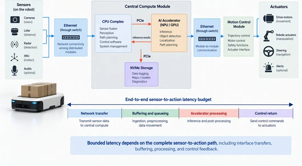
Figure 1. Bounded latency across the sensor-to-action path.
Consider a warehouse autonomous mobile robot, or AMR. The AMR may contain sensing, compute, and control modules located throughout the machine, while a central compute domain performs perception, localization, and path planning.
Ethernet can connect major modules through a network switch or Ethernet PHY. Within the central compute domain, PCIe can connect the main SoC to a local NPU, GPU, network interface, or NVMe SSD. Data from a remote module may arrive over Ethernet, move to an accelerator over PCIe for processing, and return as a control decision, while selected information is written to storage.
Each transfer adds delay, so the complete sensor-to-action path must be designed against a defined latency budget. For the AMR, the important measure is not only average response time. The worst-case delay must remain within the time available to detect an obstacle, make a decision, and issue a control command.
Meeting that latency budget depends on more than link speed. System partitioning, network topology, buffering, software behavior, and traffic management all affect the end-to-end response. The individual links may meet their respective performance targets while the complete path still misses the application’s timing requirement.
At this level, Ethernet connects major modules across the machine. Individual cameras and sensors may use dedicated endpoint interfaces such as MIPI CSI-2 or other application-specific links before their data reaches a larger compute or network module. Those peripheral connections are a separate part of the architecture.
Sharing One PHY Across PCIe and Ethernet
When a product needs both PCIe and Ethernet, implementing separate PHYs can duplicate high-speed analog circuitry, clocking resources, lane infrastructure, integration work, and verification effort. That duplication matters in robots, drones, vehicles, and industrial machines, where silicon area, package size, power, thermal capacity, and cost are constrained.
A multi-protocol PHY provides another approach. Designers can use a common SerDes architecture and assign separate lanes to PCIe and Ethernet according to the connectivity requirements of the product. One group of lanes may support PCIe connectivity to a local accelerator or storage device, while another supports Ethernet connectivity to a switch, network controller, or remote module.
The clearest benefit is reduced duplication at the PHY level. Consolidating suitable physical-layer resources can improve silicon utilization and simplify floorplanning. It can also provide a common interconnect foundation for related products that require different PCIe and Ethernet lane allocations.
Potential power savings should be stated more carefully. Active lanes still consume power regardless of whether they belong to a common or separate PHY. Any reduction depends on which clocking, control, or support resources can be shared, along with the selected process, lane configuration, protocol mix, and operating conditions.
The consolidation also does not eliminate the complete PCIe or Ethernet subsystem. Each protocol still requires its respective controller, digital protocol functions, and system-level integration. A multi-protocol SerDes consolidates suitable physical-layer resources. It does not combine the PCIe controller and Ethernet MAC or PCS into one function.
Extending the Data Path Inside the Package
The PCIe and Ethernet example addresses communication across the board and the larger machine. The same architectural question extends inward when compute cores, AI accelerators, memory interfaces, and I/O functions are partitioned across multiple dies.
In this case, the die-to-die link becomes part of the primary compute path rather than a secondary packaging detail. Its latency affects how closely the separate dies can work together. Its bandwidth density determines how much data can cross the die boundary within the available package edge. Its energy per bit affects the package power budget and thermal behavior.
The link must move data between dies without eroding the benefits of partitioning. If communication cannot keep pace with computation, data movement becomes a system bottleneck. The separate dies may provide substantial compute capability but fail to behave like a cohesive system.
UCIe provides a standardized framework for this package-level boundary. The specification covers the die-to-die physical layer, protocol stack, software model, and compliance testing, and supports established protocols as well as streaming modes.
Maintaining Performance Under Concurrent Load
Physical AI pipelines do not operate as a sequence in which one type of traffic stops before another begins. Sensor data continues to arrive while inference runs. Storage writes may occur while control messages are exchanged. Die-to-die transfers may remain active while PCIe and Ethernet traffic cross other parts of the system.
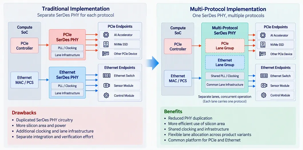
Figure 2. Comparison between traditional implementation and multi-protocol implementation architectures
This is where concurrency becomes important. In the AMR, one group of lanes may carry PCIe traffic between the SoC, accelerator, and storage, while another carries Ethernet traffic between major modules. When the selected multi-protocol PHY supports simultaneous independent links, both paths can remain active rather than serializing unrelated transfers.
The latency requirement does not change when more traffic becomes active. The architecture must keep critical transfers within their assigned latency budgets even when accelerator, storage, network, and control traffic overlap. Concurrency is useful only if the additional activity does not make system response unpredictable.
Support for more than one protocol does not automatically guarantee concurrent operation. Protocol support, configurable lane assignment, and simultaneous operation in a validated configuration are separate capabilities. Concurrent operation depends on the lane allocation, PLL resources, reference clocks, firmware, protocol configuration, and compliance requirements of the selected implementation.
These conditions need to be defined early enough to select the correct PHY configuration. Leaving the protocol mix or clocking strategy until late in the design can limit the available lane arrangements or require additional implementation work.
Validate the Complete Pipeline
Datasheet bandwidth is only a starting point. A link that reaches its target rate in isolation may behave differently once network traffic, accelerator transfers, storage writes, die-to-die communication, and control messages compete for buffers and flow-control resources.
Validation should reproduce the traffic mix expected in the real application, not only single-link peak transfers. The goal is to confirm that worst-case latency remains within the defined budget, identify where queues form, and measure how the system responds to bursts or sustained traffic.
This testing also connects interconnect with memory architecture. Buffering can absorb short-term variation, but it can also hide growing delay. A deeper queue may prevent packet loss or backpressure in the short term while increasing the time it takes for data to reach the next processing stage. Buffer depth, traffic priority, and flow control therefore need to be evaluated as part of the end-to-end pipeline.
Power and thermal behavior should also be measured under sustained activity. Physical AI systems often operate continuously, so a brief peak test may not reveal throttling, thermal buildup, or competition for power among compute, memory, interconnect, sensing, and actuation.
Explore Cadence IP:
- 10Gbps Multi-Link and Multi-Protocol PHY IP
- PHY for PCIe 7.0 and CXL
- PHY for PCIe 6.0 and CXL
- PHY for PCIe 5.0 and CXL
Conclusion
Physical AI turns interconnect into a system behavior problem. The architecture must keep end-to-end latency within a defined budget, deliver the required bandwidth within tight power, size, and thermal limits, and maintain both when several workloads are active at once.
PCIe provides local high-bandwidth attachment to accelerators and storage. Ethernet connects major modules distributed across the platform. Die-to-die interconnect links tightly coupled resources within the package. A multi-protocol PHY can reduce duplicated physical-layer resources when PCIe and Ethernet are both required, provided that the lane allocation, clocking architecture, and simultaneous operating modes are validated for the product.
The objective is not to place the fastest interface at every boundary. It is to give each data flow a suitable path and verify that the complete system remains predictable under the conditions it will encounter in operation.
Learn more about how to architect physical AI systems with design IP in Cadence’s “Designing Physical AI Systems Under Real-World Constraints” white paper.
References
Related Semiconductor IP
- 10Gbps Multi-Link and Multi-Protocol PHY IP
- PHY for PCIe 7.0 and CXL
- PHY for PCIe 6.0 and CXL
- PHY for PCIe 5.0 and CXL
- 10Gbps Multi-Protocol PHY IP
Related Blogs
- The Memory Challenge of Physical AI
- Rivian’s autonomy breakthrough built with Arm: the compute foundation for the rise of physical AI
- The Rise of Physical AI: When Intelligence Enters the Real World
- The Rise of Physical AI and Robotics: Why Hardware-Based Security is Non-Negotiable