IDS-NoC: A Scalable Interconnect Solution for Modern SoC Design

Introduction
 As SoC designs continue to grow in complexity, the communication infrastructure connecting various IP blocks becomes increasingly important. Traditional crossbar-based interconnect architectures have been widely used for connecting processors, memories, and peripherals. While these approaches work well for smaller systems, they face significant challenges as the number of connected components increases. To address these challenges, many modern SoCs are moving towards a network-on-chip (NoC) based communication architecture.
However, designing and configuring NoCs manually for different system requirements can be complex and time-consuming.
IDS-NoC™ is a configurable generator that simplifies this process by automatically generating a NoC IP based on user-defined configurations. It allows designers to configure different NoC parameters such as topology, routing algorithm, arbitration policy, and number of initiators/targets, making it easier to generate a scalable and efficient NoC for different SoC applications.
In this article, we discuss IDS-NoC, its architecture, key components, supported configurations, and overall flow of generating a configurable NoC IP for modern SoC designs.
Why a NoC?
As SoC designs continue to grow, traditional crossbar interconnects become difficult to scale. In a conventional crossbar architecture, every initiator can potentially communicate with every target through dedicated paths. As the number of connected IPs increases, the interconnect becomes larger and more complex. This leads to increased routing congestion, timing closure challenges, higher area utilization, and reduced scalability.
The NoC approach overcomes these challenges by dividing communication into packets and sending them through a network of routers.
The NoC architecture offers several advantages:
- Better scalability for growing SoC designs
- Reduced wiring congestion
- Better area utilization
- Improved throughput for large systems
These advantages make NoC a preferred communication architecture for modern SoCs. IDS-NoC builds on this architecture by automatically generating a configurable NoC IP based on user-defined system requirements, reducing manual design effort and simplifying NoC integration.
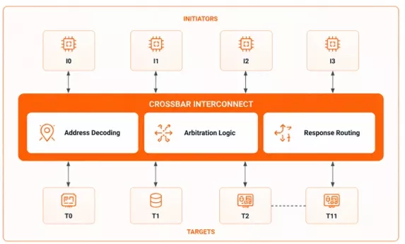
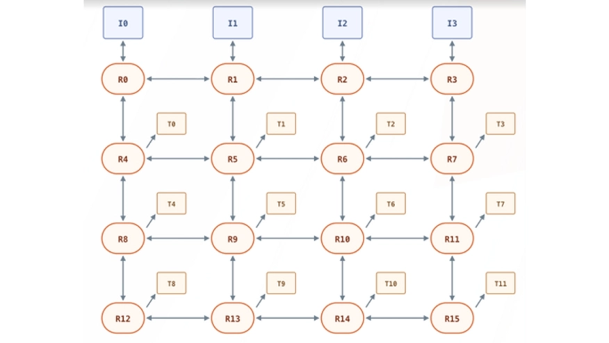
Figure 1.a: AXI4 Crossbar (4 Initiators and 12 Targets)
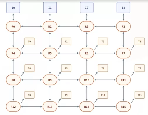
Figure 1.b: AXI4 NoC (4 Initiators and 12 Targets)
NoC Architecture Overview
IDS-NoC™ generates a configurable NoC IP based on user-defined system requirements. The generated NoC supports a mesh topology, where routers are arranged in a grid structure and connected through directional links (East, West, North, South, and Local). Processing elements such as initiators and targets are connected to the routers through Network Interfaces (NIs).
In the example design shown in Figure 2, four initiators are connected to routers on the source side of the mesh, while four targets are connected to routers on the destination side. Communication between the initiators and targets takes place through the generated NoC infrastructure.
Whenever an initiator generates a read or write transaction, it is first received by the Ingress NI. This packetizes the AXI4 transaction and, if required, divides it into one or more flits (Flow Control Units) for transmission through the NoC.
The packetized transaction is then routed through the mesh, passing through one or more routers until it reaches the destination node. At the destination, the Egress NI receives the flits, reconstructs the original AXI4 transaction, and forwards it to the appropriate target.
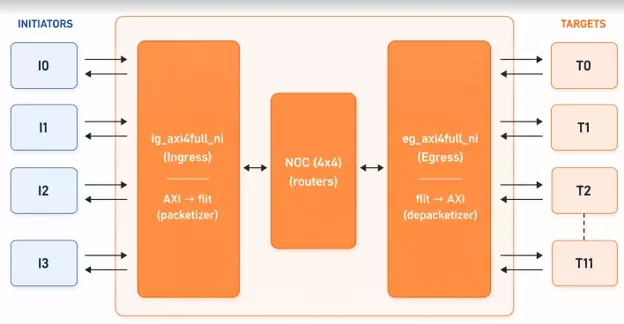
Figure 2: 4×4 NoC Block Diagram for AXI Bus
Network Interface
The NI serves as an interface between the AXI bus and the NoC. It converts AXI transactions into NoC packets and converts received NoC packets back into AXI transactions while ensuring correct data transfer.
The NI performs two important operations:
- Packetization — converts AXI transactions into smaller units called flits
- Depacketization — reconstructs the original AXI transaction from received flits
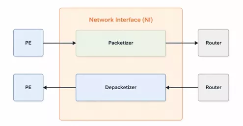
Figure 3: AXI Network Interface (NI)
Flit-Based Communication
A flit is the smallest unit of transfer within the NoC. Instead of transmitting complete AXI transactions directly, the transaction is divided into multiple flits.
IDS-NoC™ uses a fixed flit width of 72 bits. Each flit contains routing and control information along with transaction payload data. Depending on its role within a packet, a flit may be classified as:
- Head flit
- Body flit
- Tail flit
- Head-and-Tail / Single
The Head Flit carries routing information and control fields required for forwarding the packet through the network. Body Flits contain transaction data, while the Tail Flit marks the end of the packet and releases reserved network resources.
The Type field [71:70] identifies the flit category:
| Bits | Flit type |
| 00 | Body flit |
| 01 | Head flit |
| 10 | Tail flit |
| 11 | Head/Tail flit |
The VC bits [69:68] tell the router which virtual channel (VC) the flit belongs to:
| Bits | Virtual channel |
| 00 | VC0 — AW/W (write address / write data) |
| 01 | VC1 — B (write response) |
| 10 | VC2 — AR (read address) |
| 11 | VC3 — R (read data) |
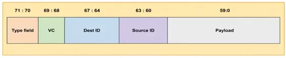
Figure 4: Flit Format
Virtual Channels and Traffic Separation
Requests and responses sharing the same communication resources can sometimes block each other. This may create a deadlock condition, preventing transactions from making progress through the network.
To address this issue, the NoC uses VCs, which allow multiple independent traffic streams to share the same physical link while maintaining logical separation.
The architecture assigns separate virtual channels for:
- Write Address and Write Data traffic
- Write Response traffic
- Read Address traffic
- Read Data traffic
By separating different transaction types into dedicated VCs, the design reduces the possibility of deadlock and improves overall network efficiency.
Router Architecture
Routers are the key communication elements within the NoC. As packets travel from a source node to a destination node, they may traverse multiple routers, each responsible for directing traffic toward the correct destination.
Each router contains the following major components:
Input Buffers
Incoming flits are temporarily stored inside buffers associated with each input port. These buffers help to absorb traffic bursts and support flow control.
Routing Computation Unit
The routing unit examines the destination information contained in the Head Flit and determines the next output direction required to reach the destination node.
Virtual Channel Allocator
Multiple virtual channels may request access to the same network resource. The Virtual Channel Allocator selects which VC receives permission to proceed.
Switch Allocator
After VC selection, requests compete for output ports. The Switch Allocator resolves these conflicts and grants access to the appropriate output path.
Crossbar Switch
The crossbar connects selected input ports to their corresponding output ports and forwards flits toward the next router.
Routing Strategy
The NoC employs deterministic XY routing. In XY routing, packets first travel along the X-direction until they reach the destination column. Once aligned, they move along the Y-direction until reaching the destination row.
Router Pipeline
Packet forwarding is performed through multiple pipeline stages:
- The first stage stores incoming flits and computes routing information
- The second stage performs VC allocation and switch allocation
- The third stage transfers flits through the internal switch fabric
- The final stage transmits flits to the next router
This pipelined architecture improves throughput and allows multiple packets to be processed simultaneously, helping ensure correct packet delivery and maintain system stability during high-traffic conditions.
Explore Agnisys IP:
Conclusion
IDS-NoC™ provides an efficient and scalable solution for generating Network-on-Chip IPs for modern SoC designs. By automating NoC generation and using packet-based communication with distributed routing, it enables scalable communication and efficient data transfer across multiple processing elements.
The generated NoC incorporates key components such as Network Interfaces, virtual channels, and pipelined routers, along with deterministic XY routing to achieve reliable and high-performance communication.
Overall, IDS-NoC™ simplifies the process of designing and integrating a configurable NoC IP while providing the scalability, performance, and flexibility required for modern SoC designs.
Related Semiconductor IP
Related Blogs
- A scalable, shader-programmable vector graphics GPU core for low-power MCUs
- 2024 Set The Stage For NoC Interconnect Innovations In SoC Design
- Boost SoC Flexibility: 4 Design Tips for Memory Subsystems with Combo DDR3/4 Interfaces
- System-on-Chip Design: Integrating Complex Systems into a Single Silicon Solution
Latest Blogs
- Tape-Out Readiness Checklist: Engineering Decisions That Prevent Costly Respins
- How Cadence DSPs Put In-Cabin AI Audio On-Chip in SemiDrive's X10
- The Fastest Path to Scalable Photonic Systems: Using Proven IP for both PIC and EIC designs
- Building Trusted AI Agents from the Silicon Root of Trust
- Heterogeneous Computing in Space