UALink Under the Hood: Why Full-Stack Verification Wins

It is tempting to picture UALink as a clean line between two accelerators: requests enter one side, responses emerge from the other. The abstraction is useful — but it conceals almost everything that makes the protocol interesting, and almost everything that makes it difficult to verify.
Verifying UALink means following a transaction the way the silicon does: down through four layers, out across one, two, or four SerDes lanes at the configured 100G or 200G serial rate, and back again, with its meaning and its bytes both intact. This blog takes that journey one layer at a time, and along the way examines a detail of the data link flit that is easy to overlook and important to get right.
The Stack, From Intent to Wire
A UALink transfer is a relay race across four layers:
Figure 1 - The UALink Protocol Stack
A transaction descends one side of the stack and ascends the other. Each layer transforms what it receives.
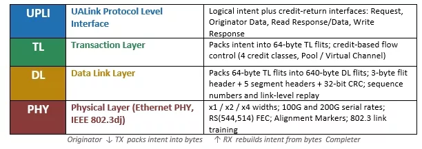
At the top, UPLI works in terms of intent: read, all-channel context that the transaction layer must preserve.
End-to-end credit flow is already visible here. The UPLI interface has request, originator data, read response/data, and write response channels, each paired with credit-return signaling. Those credits are per port and per UPLI channel: after a reset, the sender starts with no credits, and the receiver issues the initial credits before normal traffic can flow. That is why a full-stack test cannot treat UPLI as "just commands"; the command/data beats and the credit-return interfaces form the first handshake that decides whether the transaction can even enter the stack.
Counting Credits Before Packing a Byte
One layer down, the transaction layer turns that UPLI-visible credit flow into fields inside 64-byte TL flits — and, just as importantly, keeps the accounting consistent across both ends of the link.
Figure 2 - UPLI Credit Channels and TL Credit Classes
UPLI exposes credit-return interfaces per channel and per port. TL carries the corresponding flow-control information in four credit classes, each trackable as pool or virtual channel credits, so that a surge of write data cannot starve the responses working to drain it.

The mapping is the important part: UPLI presents credits on channel-specific credit-return signals, while TL encodes credit returns in flow control fields. A credit is either a pool credit (usable on any of the four virtual channels) or a virtual channel credit (bound to one). Each data credit reserves a fixed 64-byte buffer. The most elusive flow-control issues tend to arise from the interaction between these controls - initial credit release, buffer depth, return count, and virtual-channel allocation - rather than from any single one.
The 640-Byte Flit that Rewards a Closer Look
Below the transaction layer, the data link layer is where the abstraction becomes physical — and where the layout holds a genuine surprise.
Figure 3 - The 640-Byte DL Flit Layout
A data link flit is exactly 640 bytes. Of that, 628 bytes carry TL payload as 157 four-byte sectors; the remaining 12 bytes are overhead: a 3-byte flit header, five 1-byte segment headers (SH0–SH4), and a 4-byte (32-bit) CRC in the last bytes. The payload is divided into five segments - and, notably, they are not all the same size.

Figure 4 - Why the Five Segments Are Not Equal
You would expect a 640-byte flit to split into five clean, equal segments. It does not. Because non-data fields consume flit space, the last two segments carry fewer payload sectors — 31 and 30 instead of 32. A sector is 4 bytes; the 157 payload sectors total 628 bytes. The values below are taken directly from table 6-1 of the UALink200 specification.
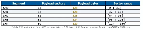
The asymmetry is deliberate. The CRC occupies the final four bytes, the flit header carries type and sequence-number information, and the segment headers define the starting content for their segments. Each segment also splits into two half-segments, which defines exactly how far to zero-fill when there is no TL flit ready to pack. The flit is not organized for sequential reading; it is organized for the wire, so that the whole 640 bytes drops cleanly into a single RS(544,514) codeword.
This is precisely the kind of structure that is invisible at the protocol level and unavoidable in practice. Locating "segment SH4, sector 12" correctly - and knowing that SH4 holds only 30 sectors, not 32 - is what separates deterministic debugging from guesswork.
Below the Flit: Lanes, Markers, and Link Integrity
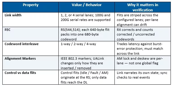
Beneath the data link layer, the physical layer maps each 640-byte flit into a single RS(544,514) codeword and distributes it across the configured link width — one, two, or four serial lanes. Here, UALink is no longer a protocol on paper but a signal on a wire, and it borrows its PHY directly from IEEE 802.3 Ethernet.
Figure 5 - Physical Layer at a Glance
Why "The Protocol Passed" Is Not the Finish Line
Each layer is an opportunity for correct intent to become incorrect behavior. These failures rarely appear when layers are tested in isolation; they surface only when a complete transaction traverses the full path and returns with its tag and data intact.
Figure 6 - One Path, Four Places to Break
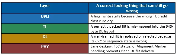
This is the essence of full-stack verification: not four independent tests stacked together, but a single transaction demonstrating that the entire path preserves both meaning and bytes. And when something does break — which, across four layers, it eventually will — that transaction can be traced from UPLI intent, through its TL flit, into its physical bytes, across the lanes, and back, revealing exactly where meaning became noise. Cross-layer visibility is what turns a multi-day investigation into a morning's work.
The Takeaway
UALink rewards close inspection. Its straightforward request/response surface rests on a genuinely well-engineered stack: credit classes that keep traffic from starving itself, a flit layout that interleaves payload around headers for the sake of clean transmission, and a physical layer that continuously realigns and self-corrects to stay up.
Verifying it well means accounting for all of that at once. A bug caught at UPLI confirms a rule; a bug caught across the full stack protects the system.
Cadence UALink VIP is designed for exactly this kind of full-stack, end-to-end verification; credit-aware, flit-accurate, lane-aware, and observable at every layer. To discuss how it fits your environment, contact Cadence Support or visit the Simulation VIP for UALink product page. You can also explore Cadence Simulation VIP solutions for broader protocol VIP support.
The protocol is the map; full-stack verification is the territory.
Related Semiconductor IP
- UALink Controller
- Simulation VIP for UALink
- UALink Subsystem
- UALink PHY + Controller
- UALink PCS IP Core
Related Blogs
- Verification of UALink (UAL) and Ultra Ethernet (UEC) Protocols for Scalable HPC/AI Networks using Synopsys VIP
- HBM Performance Verification Made Easy
- Industry's First Verification IP for Arm AMBA5 CHI-D Enables Early Adopter Success
- Managing NVME Verification Complexity
Latest Blogs
- From Bug Hunting to Engineering Methodology: Lessons from AI-Driven Development
- Manufacturing Intelligence: Turning EDA Data into Trusted Action
- Execute-in-Place: Getting More from Embedded NVM
- Rethinking RTL flows with AI-driven hybrid formal verification
- Arm and NVIDIA: Building the trusted compute foundation for the agentic AI era