Data Movement Enabling Physical AI

Most discussions around physical AI center on the models and compute that enable robots, vehicles, drones, and other autonomous machines to see, reason, and act in the physical world. Both matter, but these machines are more than the models and compute inside them. Each relies on a chain of sensors, compute, and actuators connected by a series of links. Data has to move through that chain on time and without errors for the machine to act correctly.
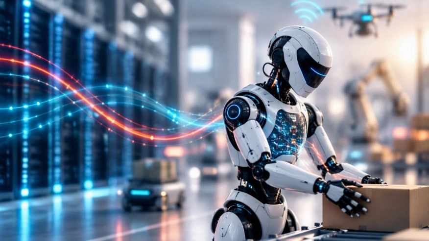 Physical AI must operate locally without depending on a connection to the data center. But the AI factory remains essential for simulation, model training, testing, and retraining before updated models are deployed back to the machine.
This post examines the three networks involved across this lifecycle. Each has its own challenges, and only one operates inside the data center.
- Inside the machine: Sensors capture the surrounding environment, onboard compute interprets the data and makes decisions, and actuators turn those decisions into physical action. This see-reason-act loop runs continuously under strict timing, reliability, and safety constraints.
- Between the machine and the data center: Outside the real-time control loop, deployed machines selectively send operational data back for analysis, simulation, and model improvement, while tested and approved model updates are delivered securely to the machines.
- Inside the data center: AI factories use collected and synthetic data to train, test, and refine the models that will ultimately run on the machine. This work distributes demanding simulation and AI workloads across large numbers of interconnected accelerators.
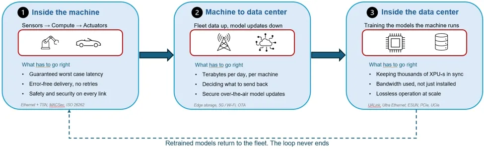
Figure 1: Physical AI runs on three networks
The rest of this post examines each network.
Inside the Machine: Latency, Reliability, and Safety
Inside a physical AI machine, data crosses several different interfaces between the moment a sensor captures something and the moment an actuator responds. Each hop uses the interface built for it, and each hop has a deadline.

Figure 2: Inside the machine, every hop is a different interface with a deadline
Cameras, radar, and lidar connect to compute over sensor interfaces such as MIPI CSI-2 and automotive SerDes, or over automotive Ethernet where sensors are aggregated by a zone controller. Inside the compute module, the NPU, CPU, and memory talk over an on-chip interconnect and memory interfaces such as LPDDR. Traditionally, the CPU, NPU, and other processing elements have been integrated into a monolithic SoC, but we are seeing more designs move toward chiplet-based architectures connected over UCIe.
Storage and additional accelerators attach over PCI Express® (PCIe®) and Compute Express Link (CXL). Commands go out to motors, brakes, and joints over deterministic networks: Time-Sensitive Networking (TSN) Ethernet in vehicles, EtherCAT in robots, and controller area network (CAN) for simpler nodes. Humanoid platforms coordinate 30 to 40 servo axes this way with sub-millisecond synchronization.
While the interfaces differ, the requirements do not, and three of them govern every hop:
Worst-case latency
A control loop does not care about average delay. It cares whether the slowest transfer still arrives on time. On the sensor side, that means a frame has to be in memory before the model needs it. On the actuator side, it means a command has to reach the motor before the next control cycle. Deterministic networking exists for this: TSN on Ethernet aligns every node to a common clock and reserves slots for control traffic, so a brake command is never queued behind a camera frame. The same idea, a bounded and predictable delay rather than a fast average, has to hold on PCIe, on the memory interface, and on the die-to-die link once chiplets arrive, or the deadline is missed somewhere else in the chain.
Reliable delivery
In a data center, a dropped packet can often be retransmitted without affecting physical safety. Inside a machine, a lost brake command or joint update may not be recoverable within the control deadline. A retry that completes inside the link, in nanoseconds, is acceptable. A retry that reaches software is not, which is why error correction, link-level replay, redundancy, and fault detection are built into the interface itself rather than handled above it.
Safety and security
The interfaces have to support functional safety through fault detection and diagnostic coverage, enabling the system to meet ISO 26262 and applicable Automotive Safety Integrity Level (ASIL) requirements in vehicles, or IEC 61508 and applicable Safety Integrity Level (SIL) requirements in industrial and robotic systems. And every link has to be secured at line rate. A spoofed sensor frame in a data center is a data breach. In a vehicle, it is a collision.
The interfaces inside the machine are part of the control system, not data pipes.
Between the Machine and the Data Center: Volume, Selection, and Secure Updates
The link between a deployed machine and the data center gets the least engineering attention because no single packet on it is time-critical. Nothing crashes if an upload is late. But this is the link that determines whether the model on the machine improves over time, and it has its own three problems.
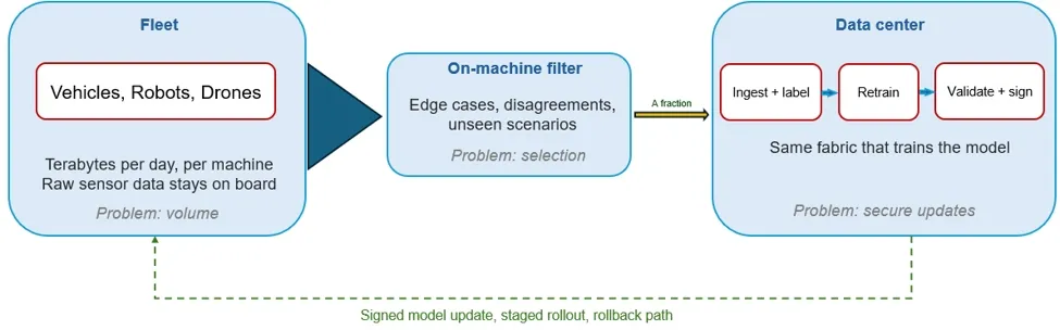
Figure 3: Between the machine and the data center, a little data goes up, and one model comes down
Volume
A deployed autonomous vehicle is commonly estimated to generate several terabytes of sensor data per day, with some operators citing 4 – 5 TB per hour of raw data. A fleet of a few thousand machines produces more raw data in a day than it can practically upload, and far more than a data center can usefully label. The raw stream has to stay on the machine. The fraction that leaves is compressed and batched, sent opportunistically when the machine is on Wi-Fi at a depot or charger, or pulled over a wired service port such as USB4, rather than in real time over cellular. The in-machine network has a role here that is easy to miss: the same in-machine backbone that feeds the compute module also has to feed on-board storage and the telematics unit without stealing bandwidth from the control loop.
Selection
Choosing that fraction of data that goes back is a design decision that shapes the next model. The useful data is the data the current model handled badly: scenarios where its confidence was low, it disagreed with a human driver or operator, a safety intervention fired, or a newer model running in shadow mode would have chosen differently. That triage runs on the machine, on the same compute that runs inference, which means part of the edge compute budget is spent deciding what the data center should learn from. Right-sized inference includes providing enough compute to run the model and select useful data without exceeding the machine's power, thermal, and size limits. The better the selection, the smaller the upload and the faster the model improves.
Secure updates
The retrained model comes back over the air, and this is where the link becomes safety-critical after all. An update changes how the machine behaves. Every deployed machine has to verify that the update was signed by the right authority, has not been altered in transit, and is the version intended for that hardware. Rollouts are staged, beginning with a subset of deployed machines and retaining a path to rollback if the new model behaves unexpectedly. Secure model delivery is one part of trusted execution, which protects data, models, and devices across the full lifecycle. Vehicle regulation now requires this: UN Regulation No. 156 mandates a software update management system for type approval, and ISO 24089 defines the engineering process behind it. Robotics fleets do not yet face the same rules, but the operators running them face the same risk.
This exchange supports continuous model improvement after deployment. Although the machine operates independently in real time, the cadence of data collection, retraining, validation, and secure deployment determines how quickly its models can improve.
Inside the Data Center: Synchronization, Utilization, and Lossless Scale
The AI factory supports the model lifecycle of a physical AI machine, from simulation and training through testing, validation, and retraining. Its data center fabric connects the accelerators performing this work at scale
The model layer has moved from task-specific networks to foundation models. Vision-language-action models take camera input and language instructions and generate actions end to end. World foundation models create physically plausible video so that policies can train on synthetic scenarios before they interact with real objects. Simulation generates much of the training data, and model training consumes it at AI factory scale. Before deployment, the trained model's inference performance, accuracy, and reliability are tested in the data center. Once validated, the model is deployed to the machine, where inference runs locally.
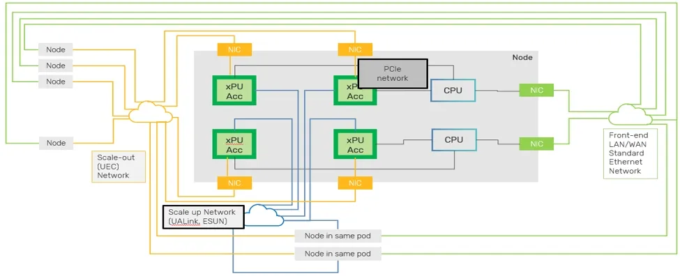
Figure 4: Inside the data center, scale-up and scale-out as one execution path
The infrastructure that trains a robot policy is also the infrastructure that trains a language model. Thousands of accelerators exchange parameters, activations, and gradients across a scale-up fabric inside the pod and a scale-out fabric across pods.
Training and testing these models place the same fundamental demands on AI infrastructure as other large-scale AI workloads: synchronization, high utilization, and lossless operation at scale.
Synchronization
Collective operations have to be completed before the workload advances. If one accelerator is waiting on a slow link, every accelerator in the group waits with it.
Utilization
Installed bandwidth is not delivered bandwidth. Retransmissions, congestion, and header overhead all reduce how much of the fabric actually carries model state. Link-level retry, credit-based flow control, and compact headers exist to close that gap.
Lossless operation at scale
A fabric of thousands of endpoints must remain lossless under load, across multiple paths, without head-of-line blocking. UALink for scale-up, Ultra Ethernet for scale-out, and Ethernet for Scale-Up Networking (ESUN) are standards being defined to do exactly that.
One Connectivity Strategy Across the Physical AI System
Inside a physical AI machine, sensor interfaces, memory links, interconnect fabrics, and in-machine networks form the real-time path from sensing to action. Separately, connectivity between the machine and the AI factory supports data collection, model training, testing, and secure deployment, but the machine does not depend on that connection to operate.
In practice, these networks may be sourced from different vendors and designed by different teams. A sensor interface may come from one supplier, a PCIe controller from another, and the Ethernet MAC from a third, while the training cluster is designed by a separate team. Each handoff can introduce differences in verification methodology, safety support, driver models, and definitions of silicon-proven IP. Connectivity IP must interoperate across these boundaries, making it a key point of integration risk.
Optimizing each network in isolation does not address integration across the broader physical AI system. Inside the machine, latency, determinism, reliability, and security directly affect real-time operation. Between the machine and the AI factory, secure and efficient data movement supports model improvement and deployment. These networks have different requirements, but they should be considered as part of one connectivity strategy.
Cadence Connectivity IP for Physical AI
Cadence provides connectivity IP for both physical AI machines and the AI infrastructure used to develop their models. Inside the machine, the portfolio includes MIPI sensor interfaces, LPDDR memory interfaces, PCIe and CXL controllers and PHYs, automotive Ethernet controllers with TSN support, USB interface IP, and UCIe controller and PHY IP for chiplet-based architectures. Cadence also provides verification IP for interface integration and verification.
Inside the AI factory, the Cadence portfolio includes High-Speed Ethernet controller IP up to 1.6T, scale-up and scale-out SerDes PHYs, ESUN-ready controller IP with link-level retry and credit-based flow control, and UALink 200G controller and PHY IP running in 3nm silicon.
For teams moving physical AI compute to chiplet-based architectures, Cadence offers the Physical AI Chiplet Platform and the Chiplet Spec-to-Packaged Parts ecosystem. These solutions bring system, CPU, accelerator, and connectivity chiplets together in a pre-verified multi-die platform.
As physical AI moves from prototypes to widespread deployment, performance will depend not only on the compute inside each machine, but also on how reliably and predictably data moves through the see, reason, act loop.
To learn more, explore the Cadence white papers "Designing Physical AI Systems Under Real-World Constraints" and "Building AI Factories With IP Solutions".
Related Semiconductor IP
- Highly scalable performance for classic and generative on-device and edge AI solutions
- MIPI CSI-2 TX Controller
- 1.6T Ultra Ethernet Controller
- HBM4E PHY and controller
- DDR5 MRDIMM PHY and Controller
Related Blogs
- How data movement defines performance for AI silicon
- Using SystemC TLM Modeling To Solve AI Data Movement Challenges
- The Missing Layer in AI Systems Design is Predictable, Scalable Data Movement
- Enabling next generation vehicles with ARM Artisan Physical IP
Latest Blogs
- Data Movement Enabling Physical AI
- How a Multi-Protocol PHY Simplifies Physical AI Connectivity
- Secure Boot on AMD Artix-7 FPGA: Getting started with KiviBoot-Tiny and MicroBlaze CPU
- From Perception to Driving Actions: Alpamayo on Chimera
- Protecting Edge AI with RISC-V CHERI: See how easily memory-safe security can be added to an AI application (part 1)