Understanding USB4 Retimers and Their Role in Gen2 and Gen3 - Link Training
USB4 systems rely on retimers to enable reliable high-speed communication across complex topologies where maintaining signal integrity over extended channels is a significant challenge. Retimers act as intermediate elements that restore signal quality at each hop by performing clock and data recovery (CDR) and retransmitting a clean, regenerated signal.
The USB4 link bring-up process follows a structured sequence from initial connectivity to high-speed operation. The process begins with lane initialization, where routers establish connectivity with the link partner through sideband communication. During this phase, the required parameters for link operation are exchanged and configured. Once initialization is complete, the router drives the transition into link training, where the link progresses toward stable high-speed communication.
The retimer operates based on its channel state machine, which follows router lane initialization and link training and performs corresponding state transitions based on link conditions on both sides.
Router: Lane Initialization
USB4 lane initialization is divided into five phases, where routers control link configuration and parameters synchronization across the topology.
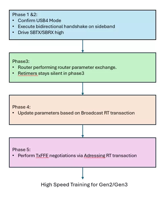
Figure 1: Five-stage lane initialization
- Phase 1 and Phase 2 – Electrical Initialization: Sideband signaling is used to establish USB4 mode, lane orientation, polarity, and electrical readiness. Retimers forward these signals to maintain continuity across the link.
- Phase 3 – Capability Exchange (Router Controlled): Routers exchange capability information such as supported link speeds, lane bonding configuration, and adapter capabilities. During this phase, the retimer does not actively participate in protocol decision-making and remains transparent, forwarding sideband transactions without modification.
- Phase 4 – Parameter Distribution (Broadcast RT): Routers distribute final link parameters using Broadcast RT transactions, including link speed and lane configuration. Retimers update their internal configuration based on these broadcasts and propagate them across their upstream and downstream ports to ensure consistency across the topology. When a Retimer detects an LT_Resume Transaction on any USB4 Port, it shall transition to phase 5.
- Phase 5 – Equalization (TxFFE Negotiation): Equalization is performed using addressed RT transactions between directly connected link partners. TxFFE parameters are negotiated independently for each segment, allowing per-hop optimization before high-speed training.
Retimers detect the receiver SLOS symbol and begin transmitting CL_WAKE1.X using a local clock once Rx Active is detected. After completing training across all segments and meeting the required clock switch conditions, the retimer transitions from the local clock to the recovered clock. It then stops generating training symbols and begins forwarding the received bit stream, moving the link into steady-state data operation.
Retimers: Channel State Machine
The retimers follow a channel state machine that aligns with the router-driven link initialization and training flow, tracking receiver activity and adapting as the link progresses. They align with the incoming signal and transition toward stable data transfer as training completes. As shown in the figure below, this sequence ensures proper synchronization before steady-state data forwarding.
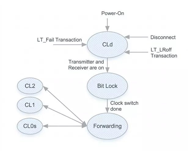
Figure 2: Retimer channel state machine
- CLd (Channel Detect): State where retimers wait for receiver activity and detect the presence of a valid signal on the channel.
- Bit Lock: Retimers enter this state once activity is detected on the receiver side. In this state, the receiver achieves clock/data recovery (CDR) and ensures reliable sampling of the incoming data, enabling proper Rx equalization and further link training progression.
- Bit Forwarding: In this state, retimers use the recovered clock and forward the received bit stream directly from receiver to transmitter without modifying the data.
Training Sequence Flow: Retimers
The table illustrates the packet flow during link initialization and transition into link training between two routers with two retimers present in the path.
| Step | Router A | Retimer 1 | Retimer 2 | Router B |
| 1 | Broadcast RT-> | Update-> | Update-> | |
| 2 | <-Update | <-Update | <-Broadcast RT | |
| 3 | LT_Resume-> | Forward-> | Forward-> | Detect |
| 4 | Detect | <-Forward | <-Forward | <-LT_Resume |
| 5 | SLOS1 -> | CL_WAKE1.1-> | CL_WAKE1.2-> | |
| 6 | <-CL_WAKE1.2 | <-CL_WAKE1.1 | <-SLOS1 | |
| 7 | CL_WAKE1.2-> | |||
| 8 | <-CL_WAKE1.2 | |||
| 9 | SLOS1 -> | SLOS1 -> | SLOS1 -> | SLOS1 |
| 10 | <-SLOS1 | <-SLOS1 | <-SLOS1 | <-SLOS1 |
| 11 | Link Training (forwarding state) |
Link Training (forwarding state) |
Link Training (forwarding state) |
Link Training (forwarding state) |
Table 1: Packet flow in retimers
- Steps 1 – 2 (RT Broadcast and Update propagation): Router A initiates link bring-up by broadcasting RT packets. Retimers receive these packets and update the information before propagating it toward Router B. The same update flow is mirrored back from Router B toward Router A.
- Steps 3 – 4 (LT_Resume handshake and detection): Router A sends LT_Resume to trigger link initialization. Retimers transparently forward this signal, enabling Router B to detect link activity. The acknowledgment follows the reverse path through retimers.
- Steps 5 – 8 (CL_WAKE exchange through retimers): CL_WAKE ordered sets are generated by the retimer with each retimer, sending CL_WAKE1 corresponding to its retimer index. This stage ensures link partners are synchronized before progressing further.
- Steps 9 – 10 (SLOS1 exchange): SLOS1 ordered sets are transmitted and propagated across both retimers without modification. At this stage, retimers primarily act in forwarding mode, maintaining the integrity of training sequences.
- Step 11 (Transition to Link Training): Once ordered set exchanges are complete, all components (routers and retimers) transition into link training. Retimers operate in forwarding mode, directly passing received bits to the transmitter without alteration.
Verification Challenges for the Retimers
Verification of USB4 retimer topologies presents challenges in ensuring the correct propagation of training sequences across multiple segments. Each retimer must receive, regenerate, and forward sequences while maintaining signal integrity and timing alignment.
Retimer identification and topology discovery ensure correct mapping of logical indices across the chain. Any mismatch can lead to incorrect targeting of training transactions.
Lack of proper verification of retimer behavior can lead to link instability or failure in multi-retimer topologies. If such issues are identified post-silicon, time-to-market is impacted due to the additional effort required for debug and re-verification.
Cadence has a mature verification IP solution for the verification of various topologies of retimers in a USB4 design, with verification capabilities provided to do a comprehensive verification of these topologies.
Learn more about Simulation VIP or reach out to our Cadence Verification IP experts for further information.
Related Semiconductor IP
- Simulation VIP for USB4
- USB4 VIP
- USB4 v2.0 Verification IP
- PCIe Controller for USB4 with AXI
- PCIe Controller for USB4
Related Blogs
- USB4: Higher Performance and Combined Data, Display, and Power
- Cadence Leads the Pack: The First VIP for USB4 is Here!
- USB4 Is Here - USB-IF Ratifies USB4 specification
- USB3, PCIe, DisplayPort Protocol Traffic Finding its Way Through USB4 Routers
Latest Blogs
- Embedded Security explained: Secure boot for embedded systems
- World's First Standards-Compliant 112G PHY IP for Linear Optics: A Turning Point for AI Interconnects
- One Key for Every Door: How Aliro Extends the UWB Digital Key Beyond the Car
- Reprogrammable Post-Quantum Security for SoCs: Why Crypto-Agility Matters
- Designing the Beam Steering Core for a C-Band AESA: A Look at VSI's VBF0644 GaAs Beamformer IC